Gas purge valve

Inactive Publication Date: 2006-03-21
A R I FLOW CONTROL ACCESSORIES LTD
View PDF4 Cites 7 Cited by
  • Summary
  • Abstract
  • Description
  • Claims
  • Application Information

AI Technical Summary

Benefits of technology

[0019]An advantage of this arrangement is that the valve may be inactivated and easily reactivated on demand.
[0022]It is desirable for a valve according to either of the applications of the present invention., to be tamper-proof, so that it is not possible to override it and “steal” water. Accordingly, a cap is fitted over the valve housing, to thereby prohibit tampering with the valve through the gas outlets.
[0024]Preferably, a first portion of the sealing member, adapted to bear against the first valve seating, is of lesser rigidity than a second portion, adapted to bear against the second valve seating. To increase sealing engagement of the sealing member with the respective seatings of the gas outlets, the second portion of the sealing member comprises a cushioned sealing portion engageable by a corresponding biasing portion of the float member biasing it into sealing engagement with the outlet valve seatings.
[0026]To increase the sealing force acting on the sealing member when it is engaged with the seatings of the gas outlets, one of the first portion of the sealing member and the corresponding second valve seating is indented with respect to the other one of said first portion of the sealing member and the corresponding second valve seating, to thereby increase the effective sealing area.
[0027]According to a particular embodiment of the invention, the valve is an inexpensive, disposable device, fitted on a water supply line, adjacent before a water flow meter.

Problems solved by technology

Air flowing through a liquid supply line may, apart from causing mechanical damage to equipment fitted on the conduit, also cause malfunctioning of different devices such as flow meters, valves and the like.
However, when air accumulates in the conduit, the float is displaced downwardly under its own weight thereby opening the outlet aperture with consequent venting of the air.
However, in view of the relatively small dimensions of the aperture, this automatic kind cannot cope with situations wherein large quantities of air have to be vented and when such a situation arises, not all the air is released and some of it passes into the line, potentially giving rise to an air lock.
However, with such a kinetic valve, once the housing thereof has filled with liquid and the float has been pressed against the large aperture so as to seal it, the valve will only reopen once the pressure in the housing has dropped to atmospheric pressure and, in consequence, the kinetic valve cannot be used for the continuous release of small amounts of air, in particular when flowing at high pressure.
Such combined valves are nevertheless of relatively bulky and expensive construction.
However, the device will also discharge of gas flowing at high flow rate and at higher pressure.

Method used


Image

  • Gas purge valve
  • Gas purge valve
  • Gas purge valve

Examples


Embodiment Construction

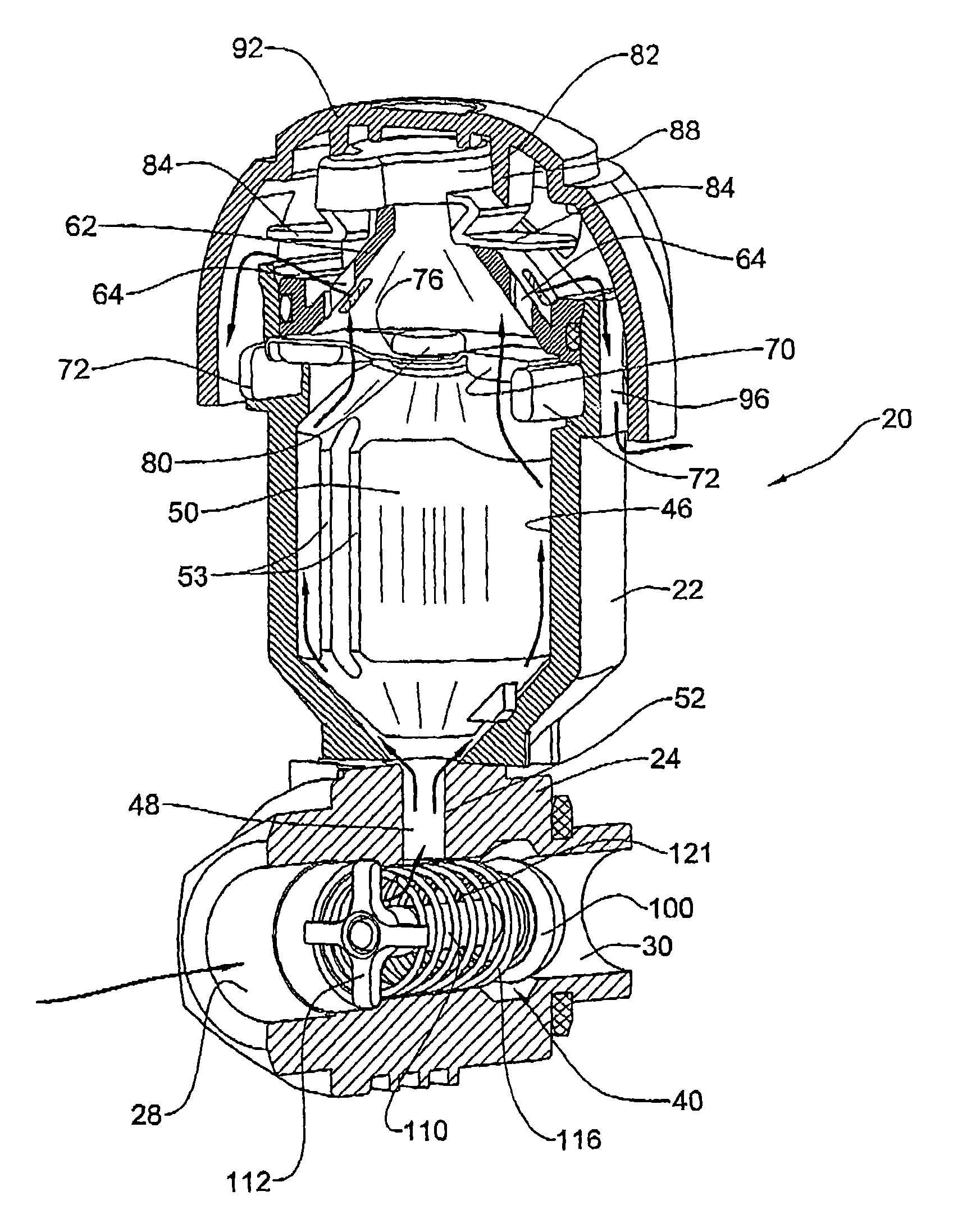
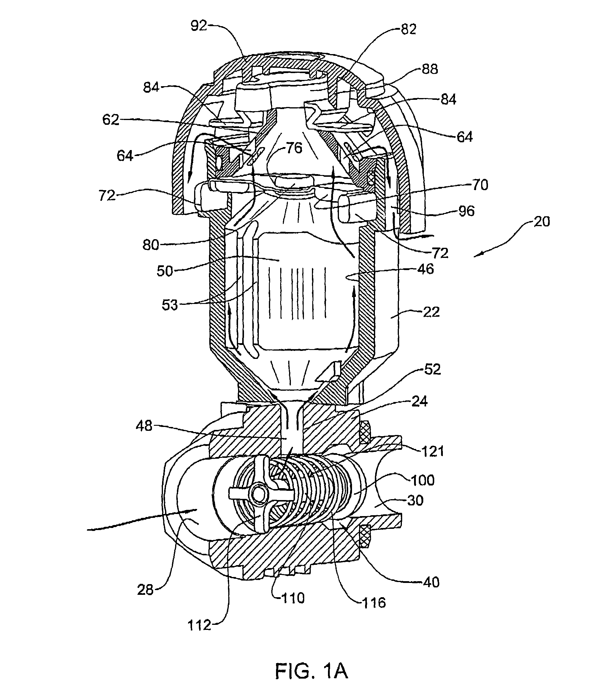
[0050]Attention is first directed to FIGS. 1 and 2 illustrating a first embodiment of a gas purge valve in accordance with the present invention generally designated 20, illustrated in. FIG. 1A in a so-called open position, namely an air releasing position and in FIG. 2A illustrated in a so-called closed position, as will become apparent hereinafter.

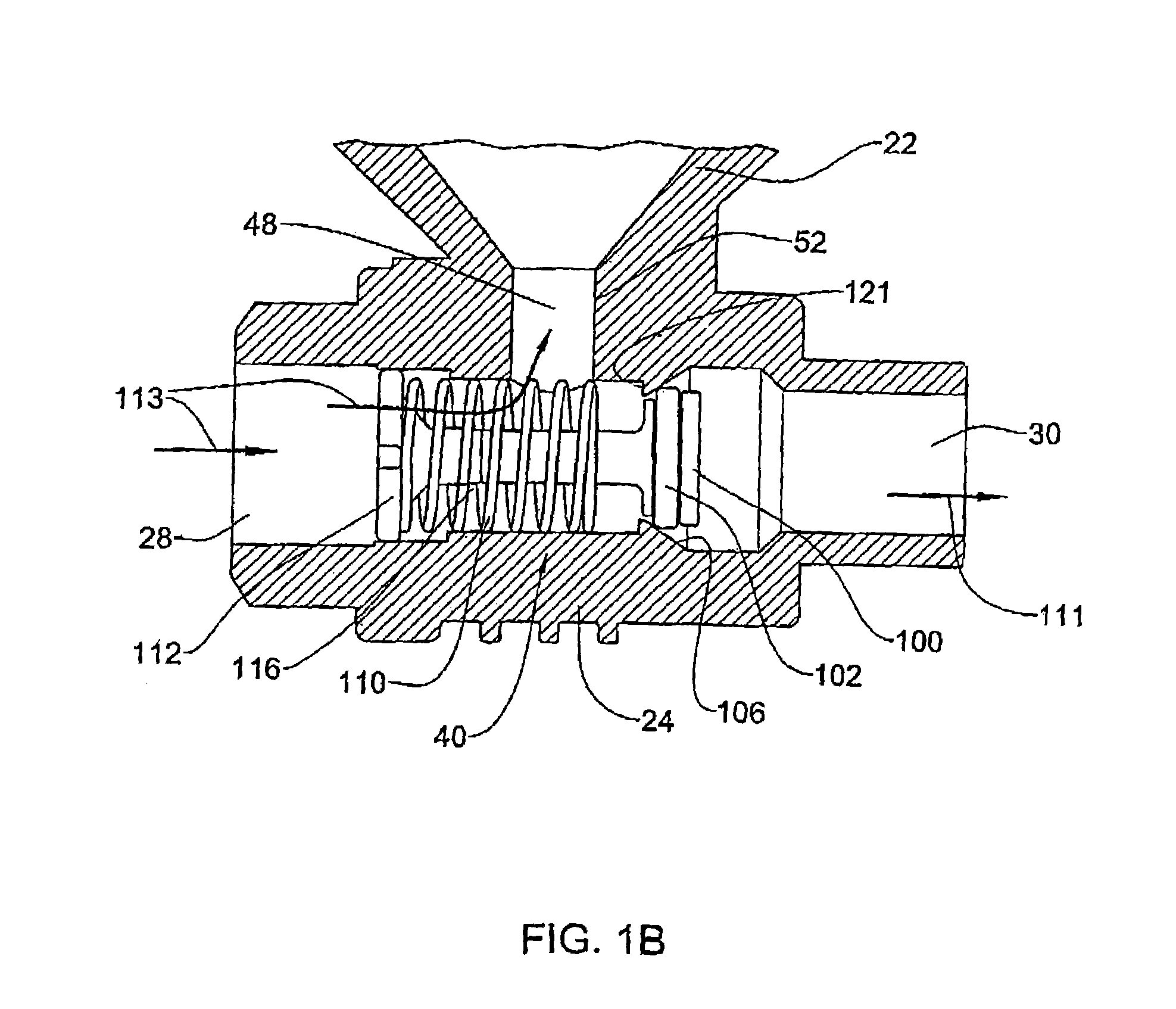
[0051]The embodiment of FIGS. 1 and 2 illustrates a structure suitable for mounting on a non-vertical conduit segment, e.g. a generally horizontal conduit. The valve 20 comprises a housing 22 which is a cylindrical structure extending essentially vertical from a liquid coupling member 24, formed with an inlet port 28 and an outlet port 30 with a flow path 32 (FIG. 2A) extending therebetween. In the present example, housing 22 is integrally formed with the liquid coupling member 24, manufactured of molded plastic material, with suitable reinforcement structural ribs. It is however appreciated that this is a mere example and the housing 22...


PUM


Abstract

A gas purge valve comprising a housing fitted with an inlet port being in flow communication with a liquid outlet port, and at least one gas outlet member, a gas flow barrier associated with the liquid outlet port, a float member displaceable within the housing between a first position adjacent the inlet port and a second position adjacent the gas outlet The at least one gas outlet is fitted with an inlet prohibiting valve, and is sealingly engageable by a flexible sealing member articulated to the float member. Buoyant displacement of the float member into the second position entails sealing of the at least one gas outlet by the flexible sealing member.

Description

FIELD OF THE INVENTION[0001]The present invention generally relates to gas purge valves and more particularly it is concerned with air release valves suitable for discharging gas at a wide range of pressure and flow rate, including substantially low gas pressure and low flow rate.BACKGROUND OF THE INVENTION[0002]Air purge valves are generally fitted to liquid conduits such as, for example, mains distribution lines or sewage distribution conduits and are designed to ensure the release of air or other gases from the conduits, thereby avoiding the production of air locks, for example, which would interfere with the flow of the liquid. Air flowing through a liquid supply line may, apart from causing mechanical damage to equipment fitted on the conduit, also cause malfunctioning of different devices such as flow meters, valves and the like.[0003]Two different kinds of gas puree valves are known. In both kinds, a float is located in a housing which is coupled at a lower end thereof to the...

Claims


Application Information

Patent Timeline
IPC IPC(8): F16K15/02E03B7/07F16K24/04
CPCE03B7/077F16K24/044E03F5/08E03B7/09Y10T137/7931Y10T137/3087Y10T137/3099Y10T137/1632F16K24/046
Inventor RYABTSEV, VLADIMIRKATZMAN, YOUVALKANDANYAN, MORDECHAI
Owner A R I FLOW CONTROL ACCESSORIES LTD
Why Eureka
Try Eureka