
Method of positioning a window covering in a sizing mechanism

Inactive Publication Date: 2006-03-07
HUNTER DOUGLAS INDS SWITZERLAND
View PDF110 Cites 36 Cited by
  • Summary
  • Abstract
  • Description
  • Claims
  • Application Information

AI Technical Summary

Problems solved by technology

However, if a cutting apparatus is to be located within an 8-foot bay environment, any vertical blind slat extending greater than 8 feet would not be able to be sized with an apparatus located within the 8-foot bay.

Method used


Image

  • Method of positioning a window covering in a sizing mechanism
  • Method of positioning a window covering in a sizing mechanism
  • Method of positioning a window covering in a sizing mechanism

Examples


Embodiment Construction

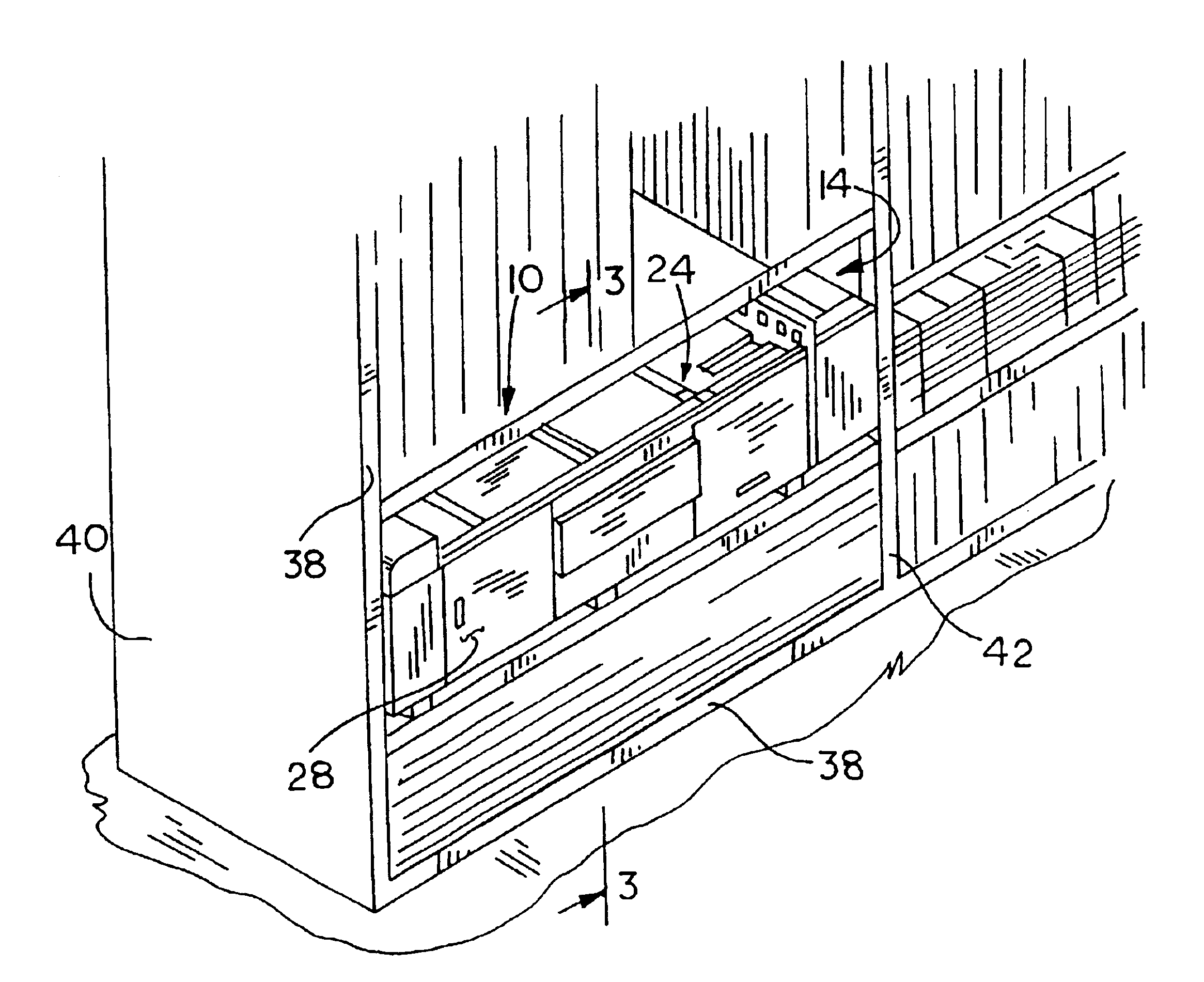
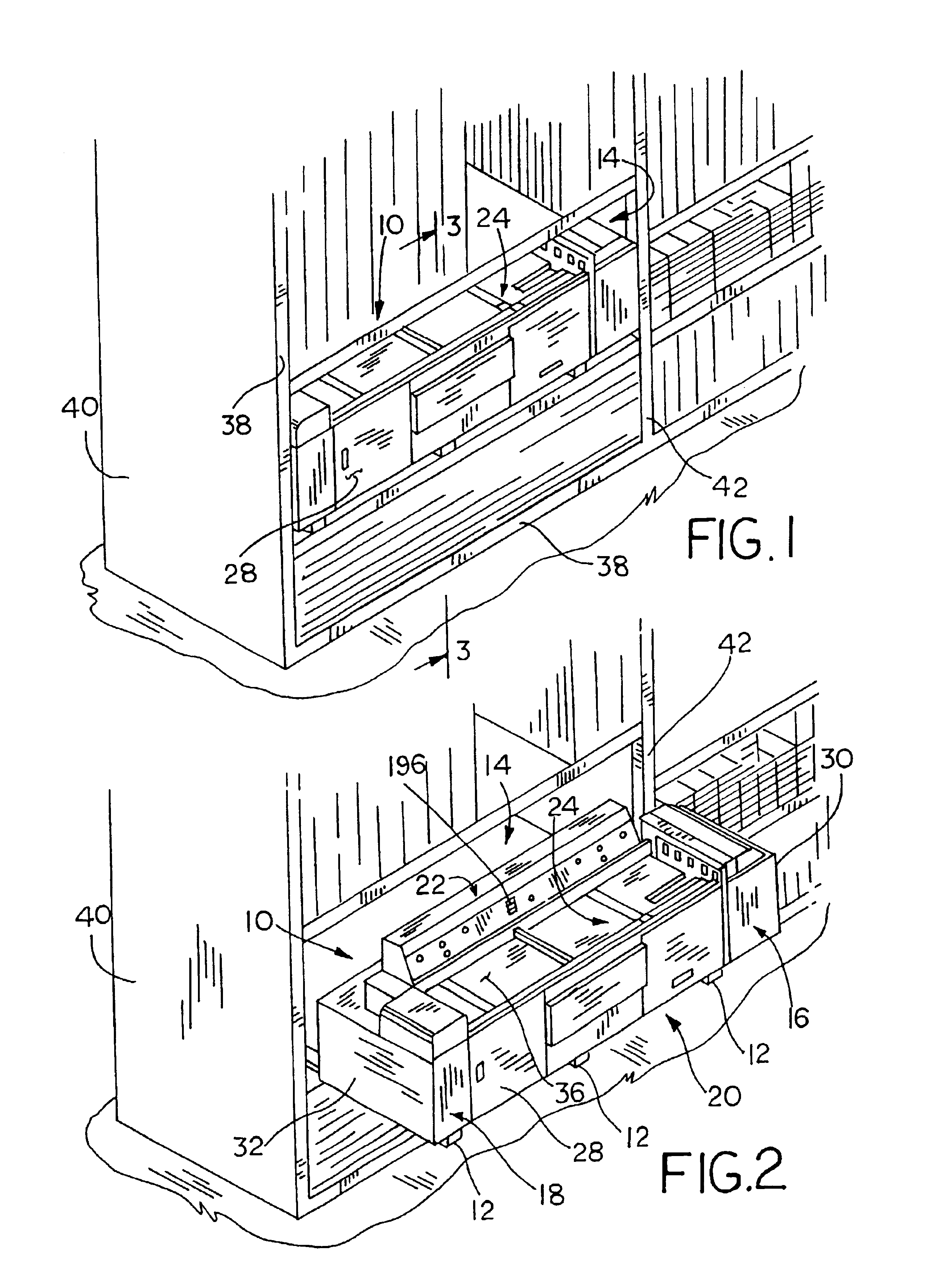
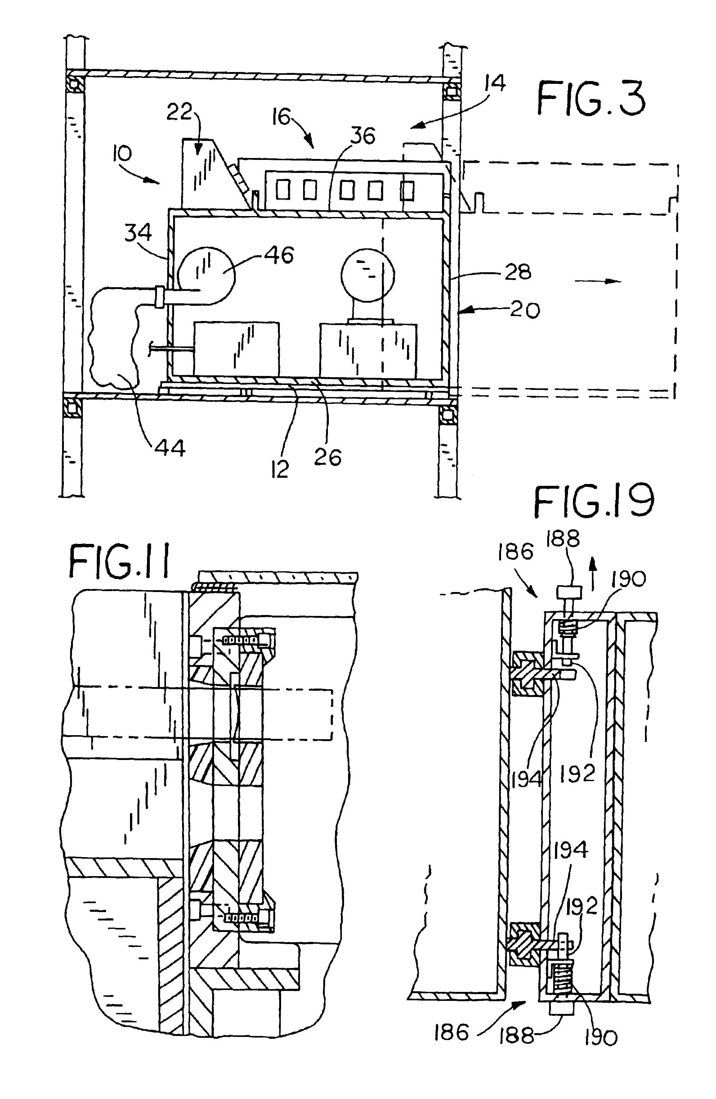
[0039]Referring now to the drawings, an apparatus for sizing both blinds and shades for window coverings is generally illustrated in FIG. 1. The blind and shade cutting center 10 is slidably movable on rails 12 in and out of a bay 14. The cutting center 10 includes a first cutting station 16 for sizing mini-blinds, pleated shades, and cellular shades. The cutting center further includes a second cutting station 18 for sizing wooden blinds and vertical blinds. The first and second cutting stations 16, 18 are supported by and located on opposing ends of a housing 20. A controller mechanism 22 allows an operator to gain access and to control the first and second cutting stations 16, 18. Further, cutting center 10 includes a center locating and measuring system 24 to position the blinds and shades to be sized.

[0040]Referring to FIGS. 2 and 17 the housing 20 of the cutting center 10 includes a bottom 26, a front wall 28, a first and second side wall 30, 32, a rear wall 34, and a top work...


PUM

PropertyMeasurementUnit
Forceaaaaaaaaaa
Widthaaaaaaaaaa

Abstract

A method of and apparatus for positioning a stock window covering in a sizing mechanism for sizing the window covering in a retail outlet includes obtaining a width specification for a finished window covering, which includes a bottom rail, a window covering material and a head rail, the method comprising. The stock window covering is disposed in a sizing mechanism adjacent a scale. The scale is calibrated from a cutting plane of the sizing mechanism, and has indicia that are twice the actual distance from the cutting plane. The center of the stock window covering is located on an indicia in the scale having a value equal to the width specification.

Description

CROSS REFERENCE TO RELATED APPLICATIONS[0001]This application is a divisional application of and claims priority to U.S. Ser. No. 09 / 911,292, filed on Jul. 23, 2001, now U.S. Pat. No. 6,604,443.FIELD OF THE DISCLOSURE[0002]The present invention relates generally to the field of window covering sizing machines and more particularly to a blind and shade cutting center.BACKGROUND OF THE DISCLOSURE[0003]Mass retail merchandisers sell a large number of window coverings directly to consumers. Standard sized window coverings are sized to a consumer's specifications while the consumer waits. The apparatus employed to size the various window coverings must be both easy to use by an employee of a retail outlet and should not require an extensive training period.[0004]Additionally, the floor space that the cutting apparatus requires should fit within the existing structure and layout of the retail outlet. Further, the cutting apparatus ideally should size a number of different types of window ...

Claims


Application Information

Patent Timeline
IPC IPC(8): B26D7/01B23D45/04B23D23/00B23D35/00B26D7/00E06B9/266
CPCB23D23/00B23D35/008E06B9/266B23D45/003Y10T29/39Y10T83/04Y10T83/0453Y10T83/05Y10T83/0586Y10T83/141Y10T83/162Y10T83/207Y10T83/222Y10T83/404Y10T83/408Y10T83/412Y10T83/654Y10T83/6608Y10T83/6656Y10T83/7487Y10T83/7493Y10T83/7593Y10T83/76Y10T83/7607Y10T83/7647Y10T83/7693Y10T83/819Y10T83/853Y10T83/857Y10T83/858Y10T83/929Y10T83/95
Inventor ROBERTS, DAVID C.CAPUTO, THOMAS A.COULCHER, JR., RICHARD D.SCHWARTZ, DAVID A.
Owner HUNTER DOUGLAS INDS SWITZERLAND
Learn More