
Driving aiding system

a technology assistive device, which is applied in the field of driving aiding system, can solve the problems of insufficient use of the driving aiding system in the prior art for the inability to check the situation of the coupled portions from the monitor image, and the troublesome driving operation to back the vehicle. to achieve the effect of facilitating the hitch coupling operation

Inactive Publication Date: 2006-02-28
PANASONIC CORP
View PDF12 Cites 78 Cited by
  • Summary
  • Abstract
  • Description
  • Claims
  • Application Information

AI Technical Summary

Benefits of technology

[0007]It is an object of the present invention to provide a driving aiding system that makes it possible for the driver to execute easily the operation to couple a hitch onto a trailed-vehicle side coupler while backing the vehicle without the assistant.
[0008]Also, it is another object of the present invention to provide a driving aiding system that is capable of aiding the execution of the backward driving operation of the vehicle in the hitch coupling operation with high precision even when the hitch is not on the image picked up by the camera.
[0012]According to this configuration, both the synthesized image (wide-range image) for displaying the wide range of the rearward direction of the vehicle containing the hitch and the extracted image (neighboring image) obtained by enlarging or viewpoint-transforming the partial area of the wide-range image containing the hitch are prepared. In the hitch coupling operation, the driver can operate the steering wheel while looking at the wide-range image and the neighboring image on the monitor screen. Since the images having different visual fields are prepared, the driver can operate the steering wheel while looking at the wide-range image when own vehicle is far from the trailed vehicle, and also the driver can operate the steering wheel while looking at the neighboring image when own vehicle comes close to the trailed vehicle, whereby the positional alignment between the hitch and the destination coupler can be achieved with good precision. If the wide-range image and the neighboring image are displayed in parallel in one screen, the screen switching operation can be eliminated. Thus, the hitch coupling operation is not interrupted to switch the screen, or there is no necessity that the hitch position should be searched on the new screen because of the screen switching.
[0014]According to this configuration, there is no need to search which part of the wide-range image corresponds to the enlarged image. Thus, the troublesome caused by the change in the monitored image can be reduced.
[0016]According to this configuration, even if the hitch is hidden from the camera, the hitch position can be checked on the screen and thus the hitch coupling operation can be facilitated.
[0018]According to this configuration, if the driver backs own vehicle while controlling the steering wheel such that a predetermined portion of the other vehicle that is coupled to own vehicle can coincide with the guide line, own vehicle can be guided to the position to which the hitch can be coupled even though the actual image of the hitch is not displayed on the screen. Thus, the hitch coupling operation can be facilitated.

Problems solved by technology

But it is a very troublesome driving operation to back the vehicle while controlling the steering wheel such that the hitch that is fitted to a dead angle position, which is not directly seen from the driver, coincides with the trailer side coupler.
Therefore, if the camera mode in which the hitch is not contained in the picked-up image of the camera is set, it is impossible to check the situation of the coupled portions from the monitor image.
As a result, there is caused the problem that the driving aiding system in the prior art is not totally useful for the hitch coupling operation.

Method used


Image

  • Driving aiding system
  • Driving aiding system
  • Driving aiding system

Examples


Embodiment Construction

[0031]An embodiment of the present invention will be explained with reference to the drawings hereinafter.

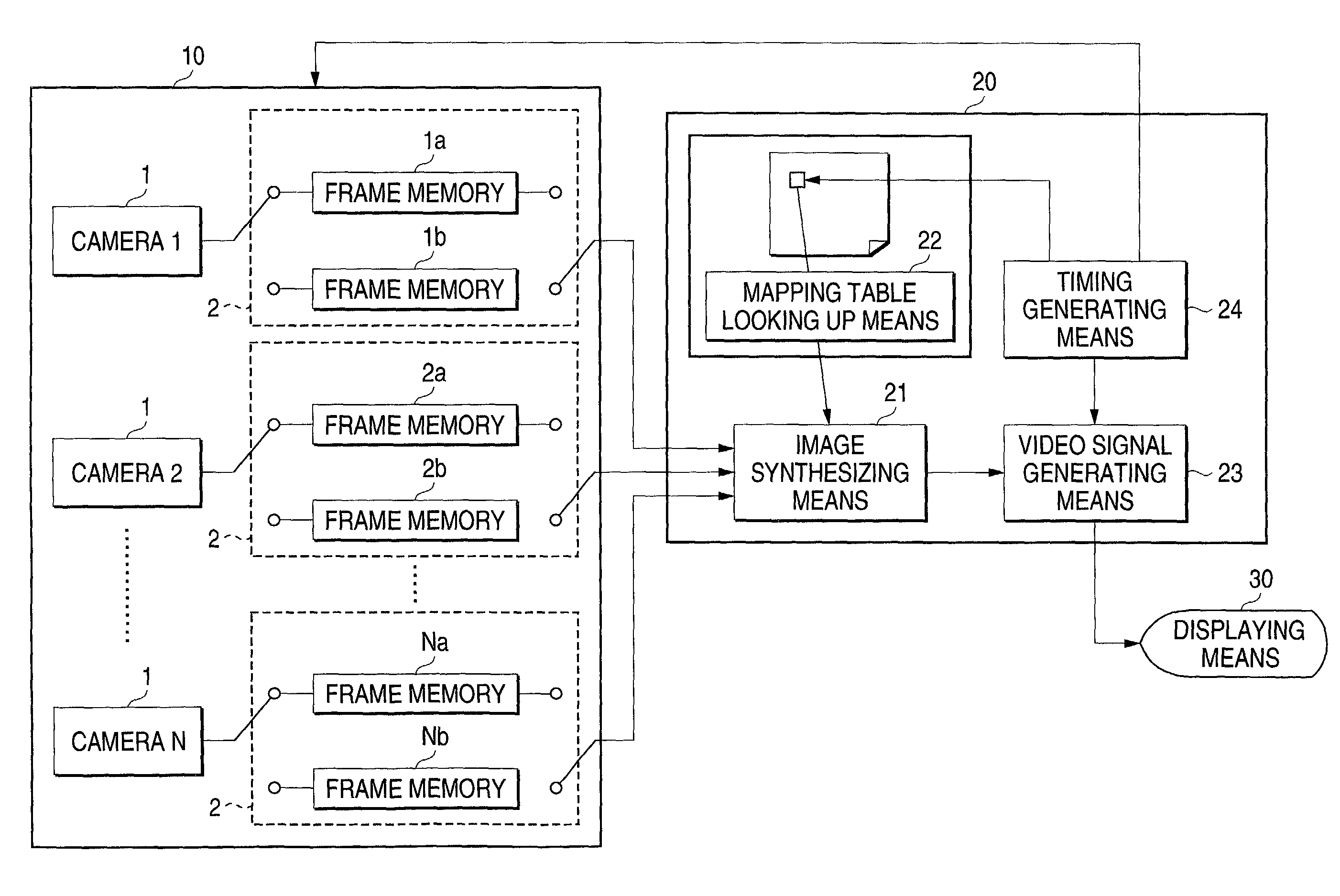
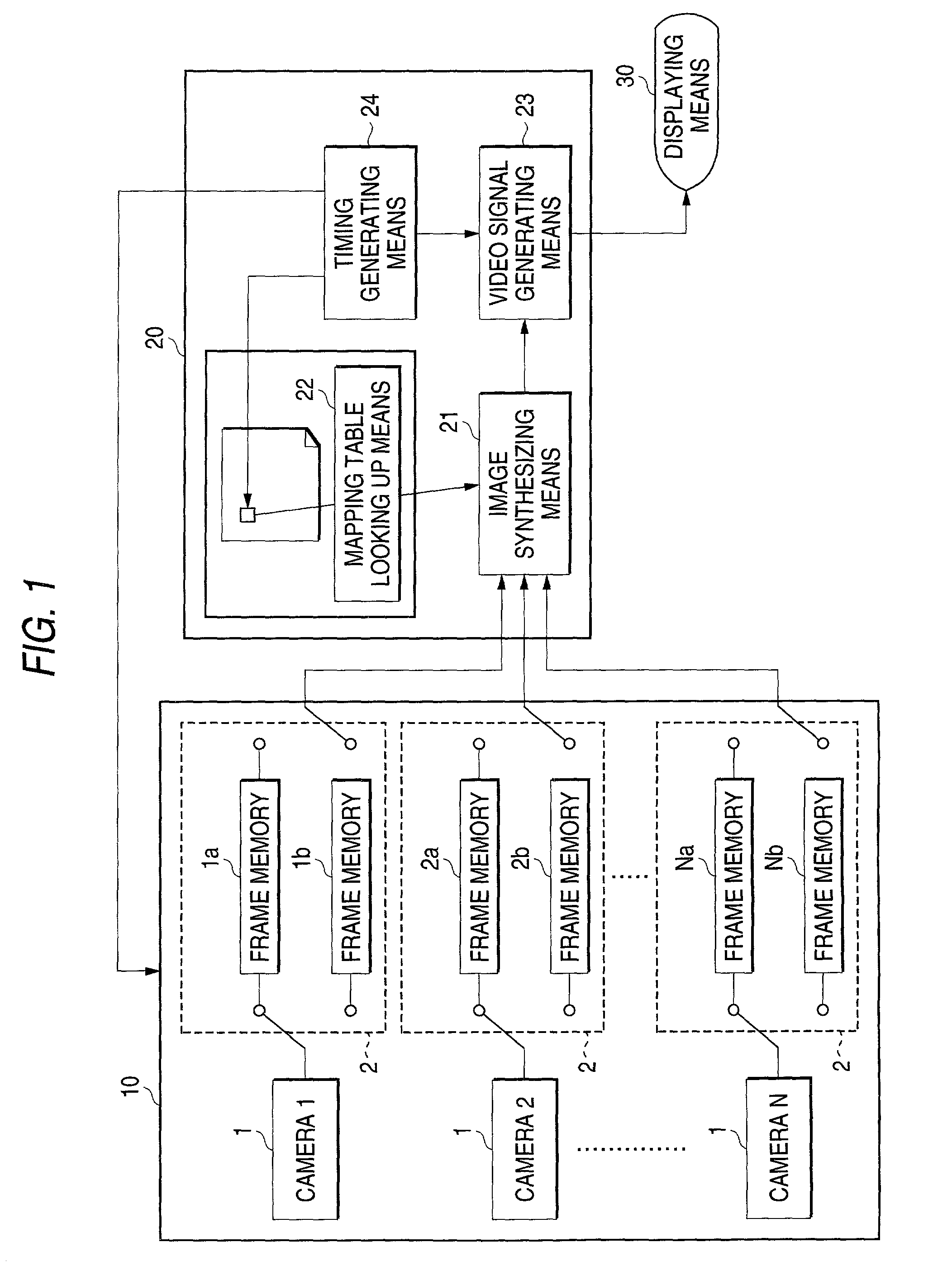
[0032]FIG. 1 is a block diagram showing a configuration of a driving aiding system according to an embodiment of the present invention. The driving aiding system according to the present embodiment comprises an image picking-up means 10, an image processing portion 20, and a displaying means 30.

[0033]The image picking-up means 10 has N image picking-up means (cameras 1 to N) that are equipped onto the vehicle. For example, the image picking-up means 10 has eight cameras in total, i.e., two cameras equipped onto the front portion of the vehicle to monitor the front side of the vehicle, two cameras equipped onto the left side portion of the vehicle to monitor the left side of the vehicle, two cameras equipped onto the right side portion of the vehicle to monitor the right side of the vehicle, and two cameras equipped onto the rear portion of the vehicle to monitor the rear side of...


PUM


Abstract

A driving aiding system includes a displaying section arranged at a position that can be looked at from a driver's seat of a vehicle, an image picking-up section for picking up an image of a rear portion of the vehicle containing at least a part of a hitch that is provided to the rear portion of the vehicle, and an image processing section for causing the displaying section to display a synthesized image that is obtained by image-processing an image picked up by the image picking-up section. A hitch image of own vehicle in addition to an image of a trailed vehicle and an image of a destination coupler are displayed on a screen of the displaying section. As a result, the relative positional relationship between the hitch and the destination coupler can be checked on the screen and thus the hitch coupling operation can be facilitated.

Description

BACKGROUND OF THE INVENTION[0001]1. Field of the Invention[0002]The present invention relates to a driving aiding system for aiding the drive by displaying an image picked up by a vehicle-equipped camera on a displaying means provided to a position that is visible from a driver's seat and, more particularly, a driving aiding system for aiding the backward driving of the vehicle in the hitch coupling operation by backing the vehicle that is equipped with a hitch, which is coupled onto a trailed vehicle, at a rear portion of the vehicle.[0003]2. Description of the Related Art[0004]The vehicles onto which a driving aiding system, which is capable of checking the safety by providing a rear-view camera to the rear portion of the vehicle and then displaying the image picked up by the rear-view camera on the monitor screen provided near the driver's seat when the vehicle is to be backed, is equipped begin to spread. For the purpose of preventing the contact with the rear obstacle when the ...

Claims


Application Information

Patent Timeline
IPC IPC(8): H04N7/00B60R11/04B60D1/00B60D1/01B60D1/36B60K35/00B60R1/00G06T1/00G06T3/00G08G1/16H04N7/18
CPCB60D1/36B60K35/00B62D15/029G08G1/16B60K2350/1084B60K2350/2013B60K2350/1088G08G1/165B60K35/28B60K2360/173B60K2360/179B60K2360/21
Inventor MIZUSAWA, KAZUFUMIOKAMOTO, SHUSAKUYOSHIDA, TAKASHIIIDA, RYOSUKEHIRAMA, YUICHIMIWA, MICHIO
Owner PANASONIC CORP
Learn More