
Delayed decision dot placement for plane-dependent CMYK error diffusion

a technology of plane-dependent cmyk error diffusion and delayed decision, which is applied in the field of printing method and system for determining color dot placement in printed images, can solve the problems of consuming a significant portion of computational resources available, slowing down the printing process, and displacing pattern, so as to achieve the effect of consuming significant computational resources and not substantially increasing computational complexity

Active Publication Date: 2006-02-21
HEWLETT PACKARD DEV CO LP
View PDF14 Cites 12 Cited by
  • Summary
  • Abstract
  • Description
  • Claims
  • Application Information

AI Technical Summary

Benefits of technology

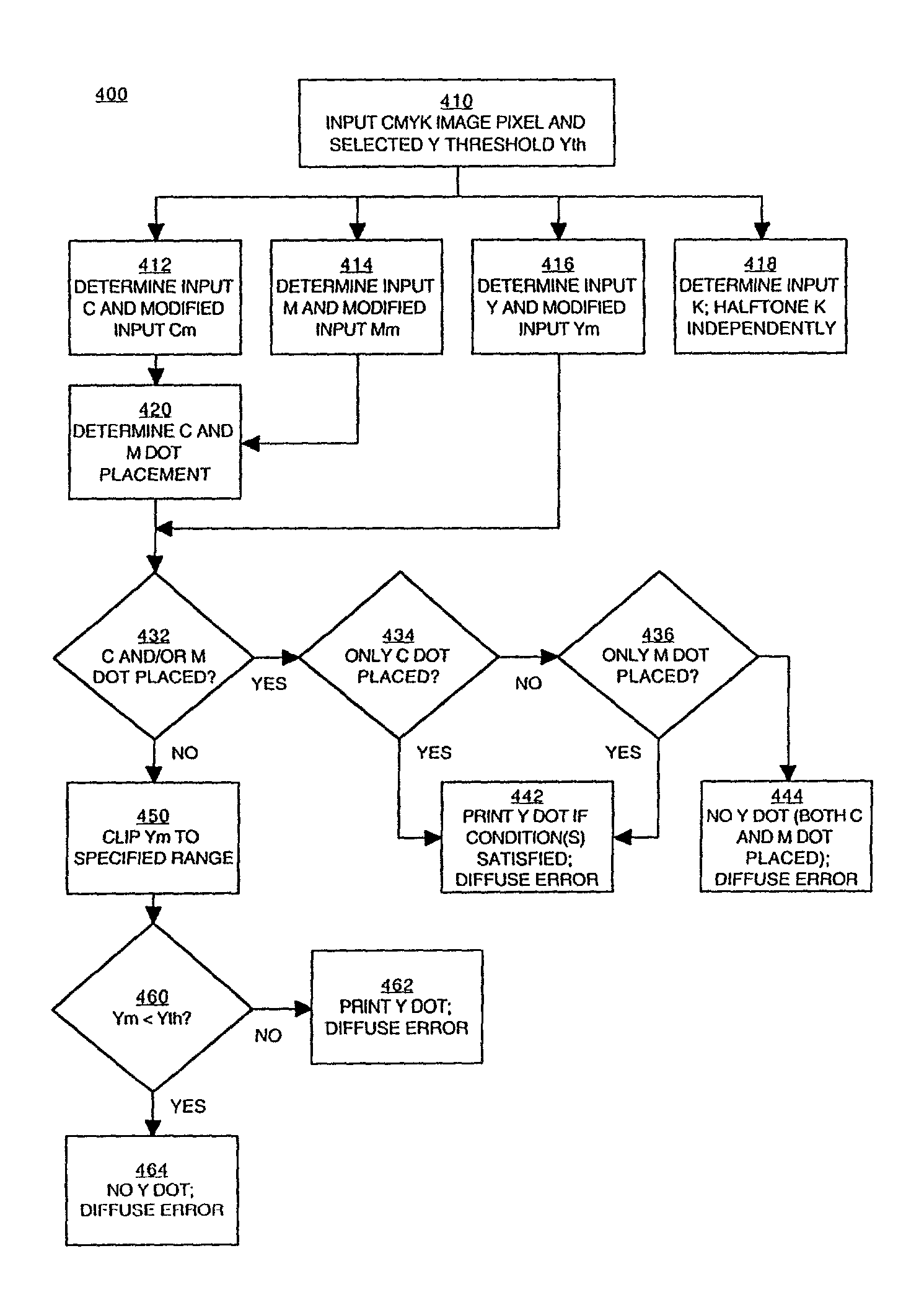
The present invention provides a method and system for printing halftone images in binary print devices. The invention allows for the placement of yellow dots based on the positions of cyan and magenta dots without significantly increasing computational complexity. The invention also minimizes color fluctuations in the printed image, resulting in superior color smoothness and improved quality. These technical effects make the invention useful in various printing applications.

Problems solved by technology

Such printers are typically binary devices, meaning that for each pixel or possible dot location on the print medium, the printer can only print at two levels per color; that is, it can either print a dot at the intensity level of the ink, or it cannot print a dot.
Although computationally efficient, such techniques can unintentionally overlap dots from different color planes or inappropriately place (clump) dots from different color planes in adjacent locations, creating an undesirable color combination or resulting in a displeasing pattern.
However, the complexity of these techniques can consume a significant portion of the computational resources available and can slow down the printing process.
However, consideration of the yellow plane together with consideration of the cyan plane and the magenta plane substantially increases the complexity of the calculations that are involved and the amount of computational resources required.
Generally speaking, if the technique described in the reference is used to consider the cyan, magenta and yellow planes together, the computational effort increases by an order of magnitude, with an attendant increase in the computational resources required.
Complexity is often reduced in prior art methods by observing that the unintended overlap or clumping of cyan and magenta dots, producing a blue tone, is the most undesirable.
Nevertheless, this approach is not completely satisfactory because it remains deficient with regard to the placement of yellow dots.
As a result of treating the yellow plane independently, interference can occur between yellow dots and cyan dots (producing inadvertent green dots) or between yellow dots and magenta dots (producing inadvertent red dots), which could cause unpleasant color fluctuations in the printed image.

Method used


Image

  • Delayed decision dot placement for plane-dependent CMYK error diffusion
  • Delayed decision dot placement for plane-dependent CMYK error diffusion
  • Delayed decision dot placement for plane-dependent CMYK error diffusion

Examples


Embodiment Construction

[0026]Reference will now be made in detail to the preferred embodiments of the invention, examples of which are illustrated in the accompanying drawings. While the invention will be described in conjunction with the preferred embodiments, it will be understood that they are not intended to limit the invention to these embodiments. On the contrary, the invention is intended to cover alternatives, modifications and equivalents, which may be included within the spirit and scope of the invention as defined by the appended claims. Furthermore, in the following detailed description of the present invention, numerous specific details are set forth in order to provide a thorough understanding of the present invention. However, it will be obvious to one of ordinary skill in the art that the present invention may be practiced without these specific details. In other instances, well-known methods, procedures, components, and circuits have not been described in detail so as not to unnecessarily...


PUM


Abstract

A printing method and system thereof are described. The locations in a printed image for a plurality of first color (e.g., cyan) dots and the locations in the printed image for a plurality of second color (e.g., magenta) dots are determined. Locations in the printed image for a plurality of third color dots (e.g., yellow) are then determined. The locations for the third color dots are dependent on the locations of the first color dots and the locations of the second color dots. The decision on where to place third color dots is thus made after, and therefore dependent on, the decisions on where to place first color dots and second color dots. Accordingly, color fluctuations in the printed image are minimized, resulting in superior color smoothness and improving the quality of the printed image.

Description

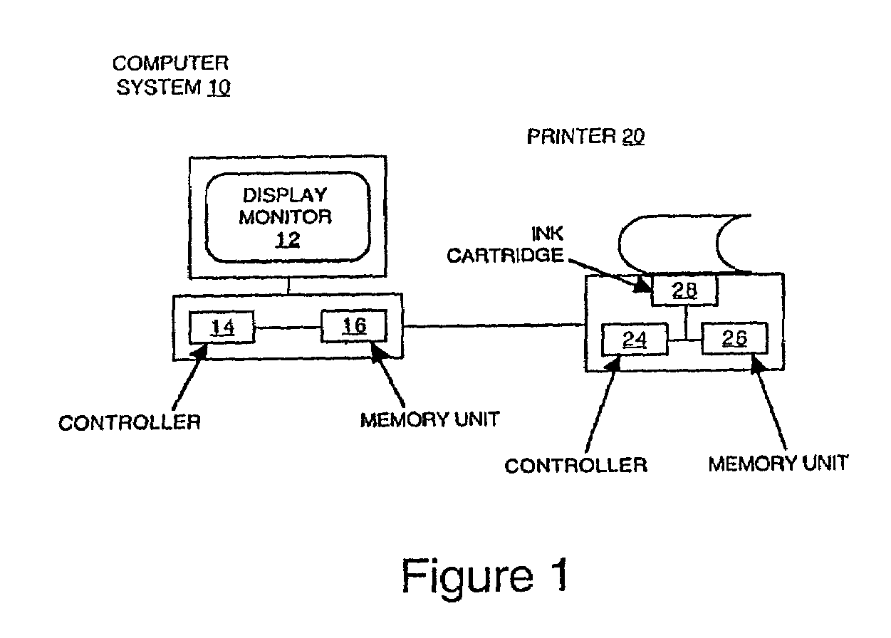
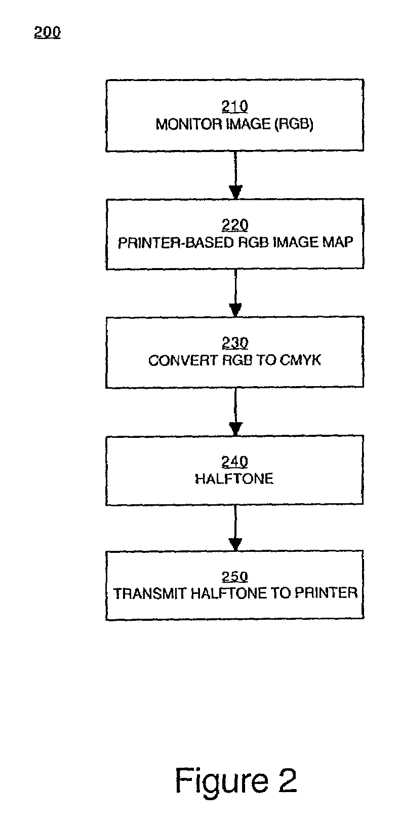
TECHNICAL FIELD[0001]The present invention relates to a printing method and system for determining color dot placement in a printed image. More specifically, the present invention pertains to a printing method and system that jointly considers three color planes when making decisions with regard to dot placement.BACKGROUND ART[0002]Rendered images (e.g., displayed or printed images) may be represented as a two-dimensional array of picture elements (pixels). The color intensity level of each pixel is chosen according to the output (rendering) device. For example, a computer monitor used for displaying an image may have 256 or more levels of intensity for each color. Computer monitors typically use the primary colors red, green and blue, which can be combined to produce millions of different colors including black.[0003]Printers (and other hardcopy output devices) are commonly provided with three ink colors (cyan, magenta and yellow) or four ink colors (cyan, magenta, yellow and black...

Claims


Application Information

Patent Timeline
Patent Type & Authority Patents(United States)
IPC IPC(8): G06F15/00H04N1/52
CPCH04N1/52
Inventor DAMERA-VENKATA, NIRANJAN
Owner HEWLETT PACKARD DEV CO LP
Learn More