
Method and apparatus for marking an escape route

a technology of escape route and method, applied in the direction of visible signalling system, electric transmission signalling system, fire alarm, etc., can solve the problems that the proposed system has not been implemented in practice, and achieve the effects of saving supply power, low luminance or radiation intensity, and low power consumption

Active Publication Date: 2006-02-14
NOVAR PLC
View PDF14 Cites 38 Cited by
  • Summary
  • Abstract
  • Description
  • Claims
  • Application Information

AI Technical Summary

Benefits of technology

[0007]This solution has the advantage that, on the one hand, it realizes the principally known running light effect on the basis of the emergency warning system which is present anyway and its installation and, on other hand, it works dynamically, meaning that it signalizes only the secure escape routes and the direction to be chosen, depending on the site of the hazard. On the one hand, the implementation costs are rather moderate because, according to the state of the art, the emergency warning units which are arranged in a distributed manner in a building are always connected to a computer-controlled central system and are powered by the same with supply voltage. On the other hand, light-emitting diodes (LEDs) with a high conversion efficiency are available as an illuminating means which therefore are able to emit light impulses of high intensity in pulsed operation without requiring a significant increase in the supply power to be provided by the central system per warning unit.

Problems solved by technology

Such proposed systems have not been implemented in practice.
Two relevant deficiencies are responsible for this fact, namely, on the one hand the considerable complexity in connection with the equipment and installation which would be necessary even in the case of a limitation to merely the light sources, and on the other hand, the fact that it concerns a kind of static solution which does not take into account that at least on larger buildings there are several separate or intersecting and mutually branching potential escape routes, and the secure escape routes to be used in an actual emergency depend on the location at which the hazard has occurred.

Method used


Image

  • Method and apparatus for marking an escape route
  • Method and apparatus for marking an escape route

Examples


Embodiment Construction

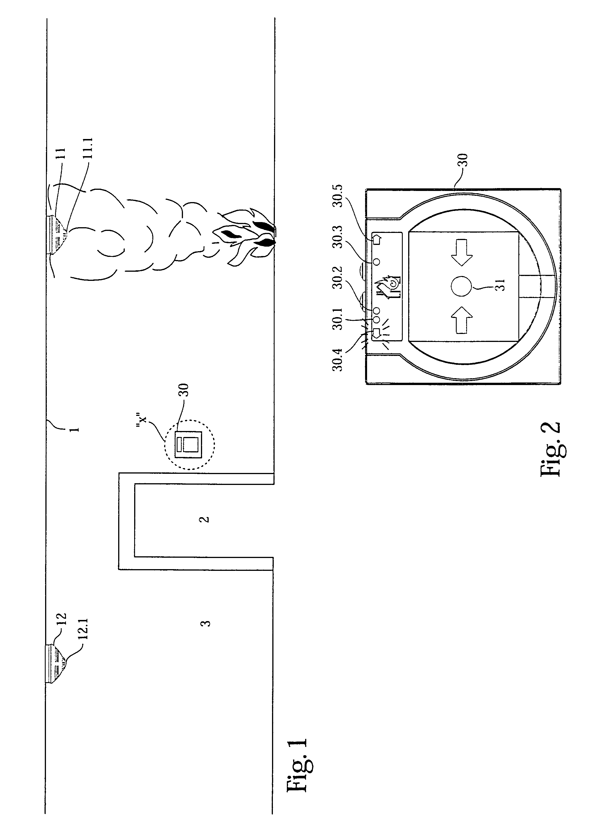
[0019]According to FIG. 1, automatic emergency warning units (here in the form of smoke alarms 11 and 12) are attached on the ceiling 1 of a corridor at predetermined intervals. A manual emergency warning unit (here in the form of a push-button warning unit 30 which is mounted on a corridor wall 3) is situated next to a door or a passageway 2 to a further corridor which can be equipped in a similar fashion with emergency warning units.

[0020]Every automatic smoke alarm 11, 12 is connected to a central system (not shown) and comprises at least one highly luminous LED 11.1, 12.1 which usually has the function of an operating state indicator or with which the warning unit is equipped additionally.

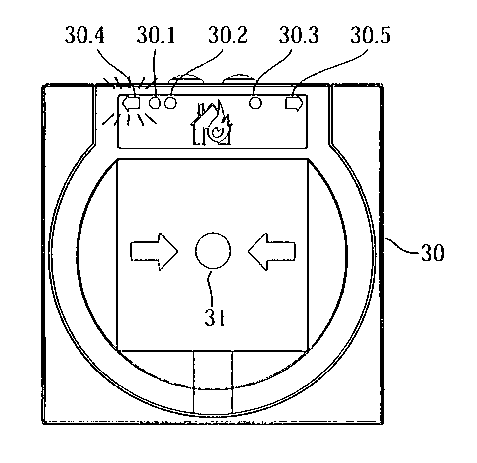
[0021]The push-button warning unit 30 comprises according to FIG. 2 the push-button 31 which can usually be activated only after breaking the glass pane, or any other mechanism which can be activated manually and which initiates the transmission of an analog or digital signal to a central syste...


PUM


Abstract

A method for signaling an escape route in a building with emergency warning units arranged in a distributed way can be realized such that the emergency warning units are equipped with luminous means that in the event of an emergency can be activated by a central emergency warning system sequentially in the manner of a running light that designates the direction of the escape route leading away from a hazard site. An emergency warning unit suitable for this purpose may include two LEDs configured as arrows facing in opposite directions, of which either can be switched into a blinking mode by the central emergency warning system in accordance with the emergency conditions.

Description

BACKGROUND OF THE INVENTION[0001]1. Field of the Invention[0002]The invention relates to a method for marking or signaling an escape route to be taken during an emergency in a building with emergency warning units which are arranged in a distributed manner and are connected to an emergency warning system. The invention further relates to emergency warning units for performing this method.[0003]2. Description of the Related Art[0004]Methods for indicating escape routes by light sources are known from DE-AS 24 41 073, the disclosure of which is incorporated herein by reference in its entirety. Such light sources are arranged in a distributed manner along the entire escape route and form a running light whose color shifts increasingly toward the color green in the direction of the safe end of the escape route or whose brightness decreases or whose rhythm slows down. The light sources are associated with sources of sound which can be excited simultaneously or delayed with the light sour...

Claims


Application Information

Patent Timeline
Patent Type & Authority Patents(United States)
IPC IPC(8): G08B5/00G08B5/36G08B7/06
CPCG08B7/066G08B7/062
Inventor BUSCHMANN, MICHAELHERSTIX, FRANKGOULET, THOMASOLLIK, WALDEMAR
Owner NOVAR PLC
Learn More