
Power line communication system and power line branching apparatus

a communication system and power line technology, applied in the field of power line communication system and power line branching apparatus, can solve the problems of power line communication failure, error rate, and communication failures that may occur in normal mode noise, so as to avoid communication failures, improve the state of indoor power lines, and be suitable for communication.

Inactive Publication Date: 2006-01-17
TDK CORPARATION
View PDF20 Cites 45 Cited by
  • Summary
  • Abstract
  • Description
  • Claims
  • Application Information

AI Technical Summary

Benefits of technology

[0015]It is a first object of the present invention to provide a power line communication system that makes it possible to perform communication between a plurality of communication devices by using an indoor power line, to avoid communication failures attributable to equipment connected to the indoor power line, and to improve the state of the indoor power line to make it suitable for communication.
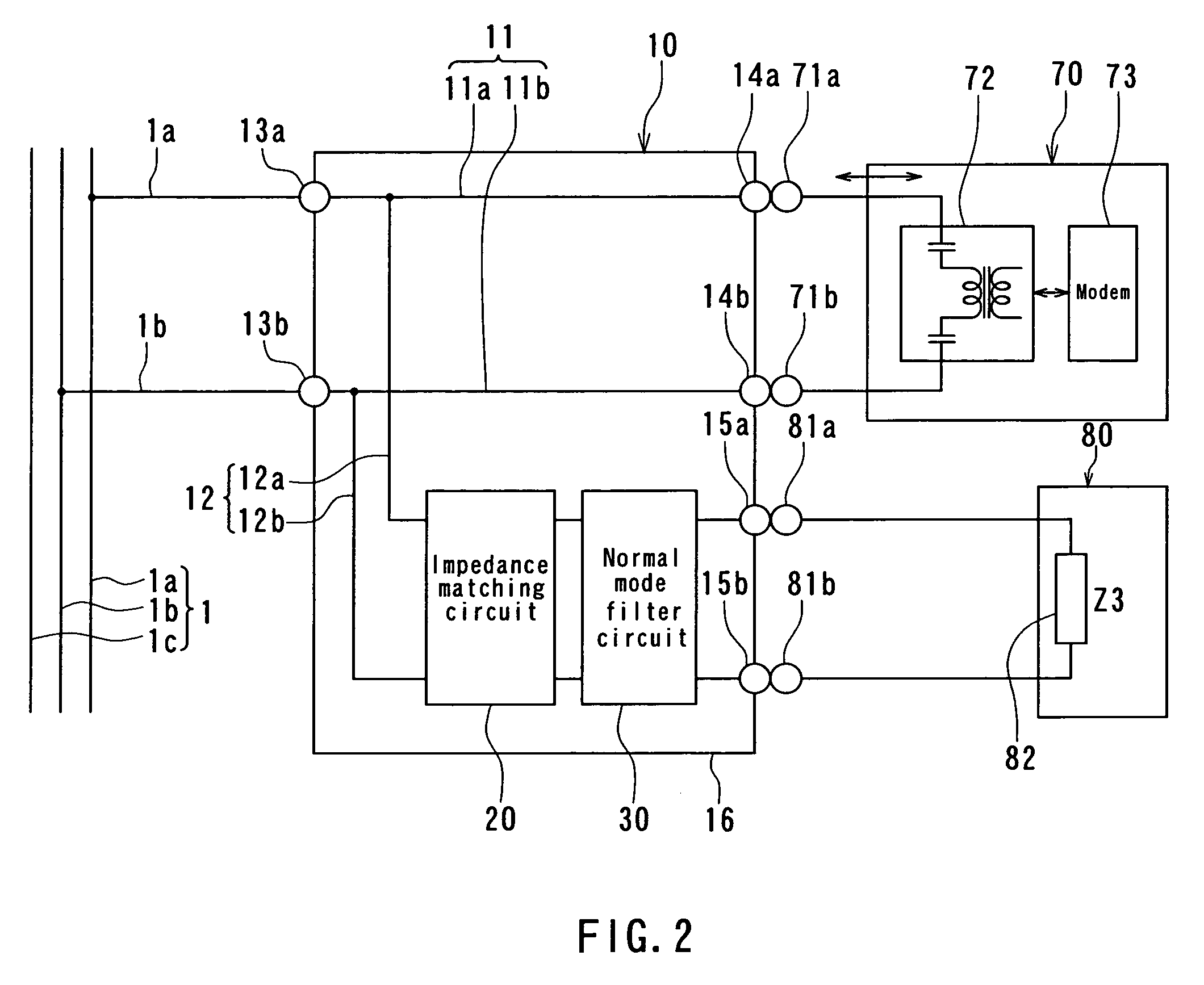
[0017]A power line communication system of the present invention allows communication between a plurality of communication devices by using an indoor power line. The system comprises: an indoor power line; a communication channel that is branched off from the indoor power line and connectable to a communication device for performing communication by using the indoor power line; a power supply channel that is branched off from the indoor power line and connectable to electrical equipment that requires electric power; an impedance matching circuit provided on the power supply channel, for setting an impedance of the indoor power line to a predetermined value; and a filter circuit provided on the power supply channel, for reducing noise occurring from the electrical equipment when the equipment is connected to the power supply channel.

Problems solved by technology

However, there arises a problem resulting from the fact that various types of electrical equipment is connected to an indoor power line that is to serve as the communication channel in power line communication.
Specifically, the equipment connected to the indoor power line can generate noise or lowers an impedance of the power line, which can result in an increase in the error rate to cause communication failures in the power line communication.
Therefore, in the power line communication, communication failures may occur from normal mode noise in particular among the noises generated by the electrical equipment.
Depending on the value of impedance of the indoor power line, signals may be reflected at connection points between the equipment for performing power line communication and the indoor power line, which results in signal deterioration.
In situations where no electrical equipment is connected to a connecting part for connecting electrical equipment to an indoor power line, such as receptacles, the connecting part makes an open termination, at which signals are reflected to thereby cause signal deterioration.
In a power line communication system, if no measure is taken against the impedance- or noise-related problems described above, communication failures can occur due to impedance variations and noises on the indoor power line.
With this technique, however, it is impossible to set the impedance of the indoor power line to a desired value suitable for communication.
Furthermore, even if this technique is employed, in situations where no electrical equipment is connected to the connecting part for connecting electrical equipment to the indoor power line, the connecting part makes an open termination at which signals are reflected.
Thus, the technique disclosed in the above-mentioned publication document cannot eliminate the problem of signal deterioration.
Due to the impedance matching circuit located between the indoor power line and the communication equipment, the electric power of signals is consumed by the resistor and this makes the signals extremely weak.

Method used


Image

  • Power line communication system and power line branching apparatus
  • Power line communication system and power line branching apparatus
  • Power line communication system and power line branching apparatus

Examples


first embodiment

[First Embodiment]

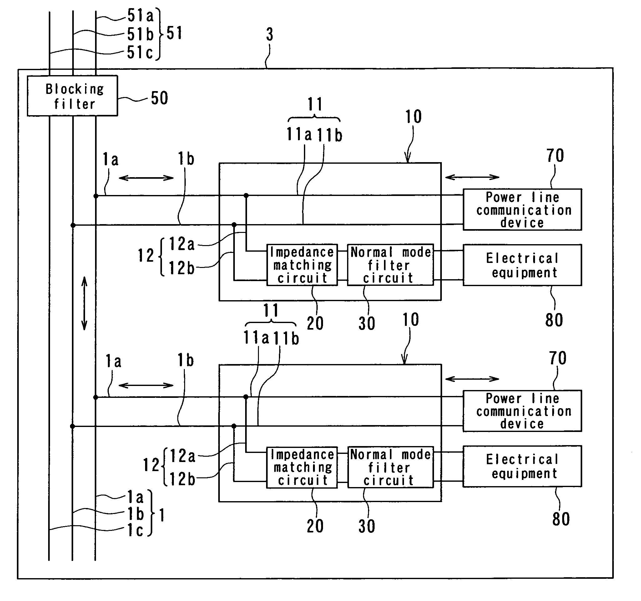
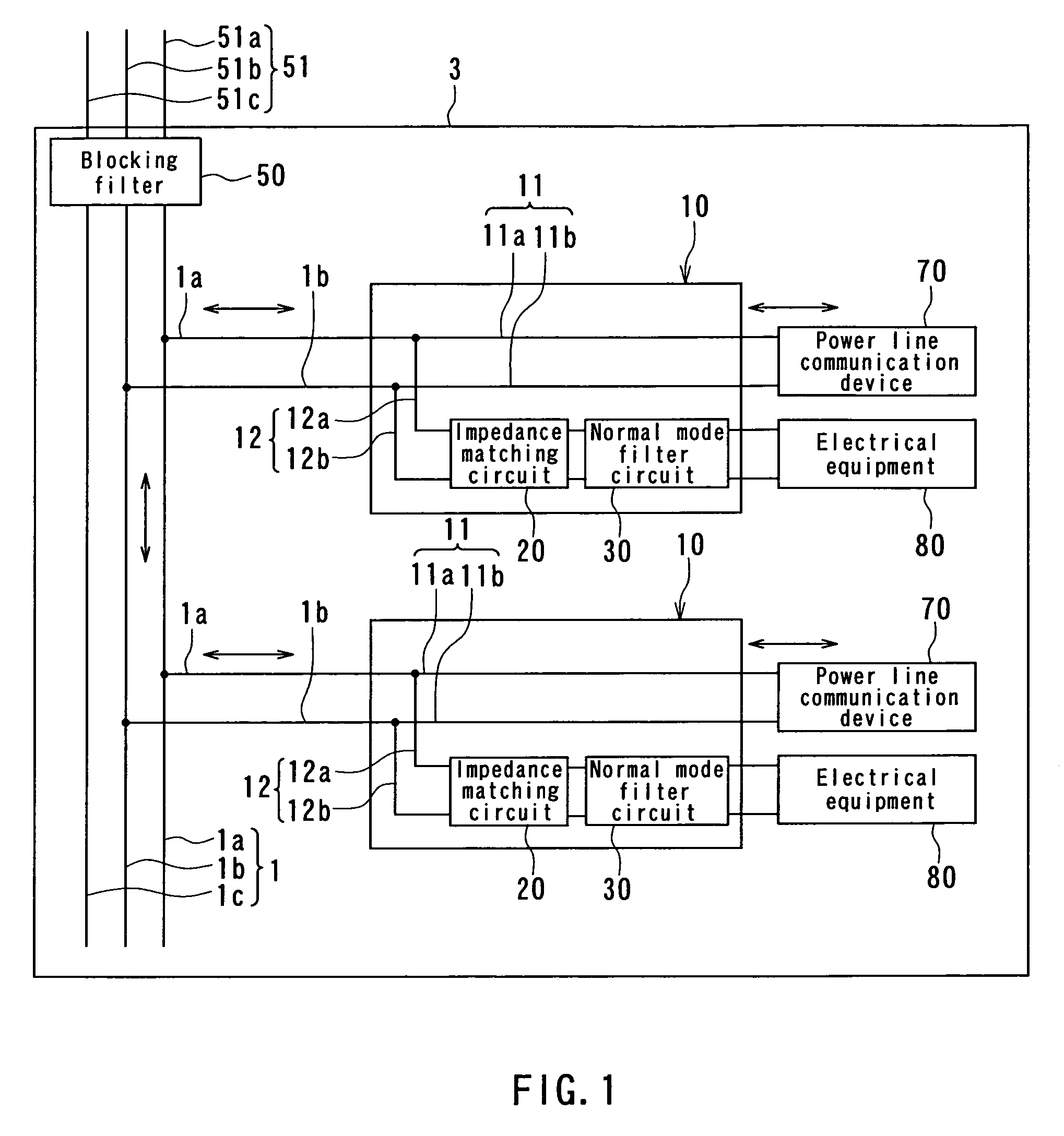
[0056]First, description will be given of a power line communication system and a power line branching apparatus according to a first embodiment of the invention. FIG. 1 is a block diagram showing a configuration of the power line communication system according to the first embodiment. As shown in FIG. 1, the power line communication system of the first embodiment comprises: an indoor power line 1; one or more power line branching apparatuses 10 of the embodiment connected to the indoor power line 1; and a blocking filter 50 connected to the indoor power line 1. The indoor power line 1 is connected to an outdoor power line 51 through the blocking filter 50. A power line communication device 70 for performing power line communication by using the indoor power line 1, and electrical equipment 80 that requires electric power carried by the indoor power line 1 are connectable to the power line blanching apparatus 10. In FIG. 1, the reference numeral 3 represents the in...

second embodiment

[Second Embodiment]

[0109]Now, description will be given of a power line communication system and a power line branching apparatus according to a second embodiment of the invention. FIG. 14 is a circuit diagram showing a configuration of the power line branching apparatus 10 according to the second embodiment. The power line branching apparatus 10 according to the embodiment has a first accommodating member 16A and a second accommodating member 16B, instead of the accommodating member 16 of the first embodiment.

[0110]The first accommodating member 16A accommodates the connecting parts 13a and 13b that are respectively connected to the conductive lines 1a and 1b of the indoor power line 1, and the device connection terminals 14a and 14b to which the power line communication device 70 is connected detachably. The first accommodating member 16A further accommodates the communication channel 11 including the communication lines 11a and 11b for connecting the connecting part 13a and the d...

third embodiment

[Third Embodiment]

[0115]Now, description will be given of a power line communication system and a power line branching apparatus according to a third embodiment of the invention. FIG. 15 is a circuit diagram showing a configuration of the power line branching apparatus 10 according to the third embodiment. The power line branching apparatus 10 according to the embodiment is detachably attachable to a typical receptacle 90 intended for power supply. The receptacle 90 has connection terminals 91a and 91b connected to the conductive lines 1a and 1b of the power line 1, respectively.

[0116]The power line branching apparatus 10 according to the embodiment has an accommodating member 17 formed as a case, instead of the accommodating member 16 of the first embodiment. In the accommodating member 17, there are provided plug-shaped connection terminals 18a and 18b, instead of the connecting parts 13a and 13b of the first embodiment. The connection terminals 18a and 18b are connected detachabl...


PUM


Abstract

A power line communication system comprises an indoor power line and one or more power line branching apparatuses connected to the indoor power line. The power line branching apparatus comprises a communication channel that is branched off from the indoor power line and connectable to a power line communication device, and a power supply channel that is branched off from the indoor power line and connectable to electrical equipment. The power line branching apparatus further comprises an impedance matching circuit and a normal mode filter circuit. The impedance matching circuit is provided on the power supply channel, and sets the impedance of the indoor power line to a predetermined value. The normal mode filter circuit is provided on the power supply channel, and reduces normal mode noise occurring from the electrical equipment connected to the power supply channel.

Description

BACKGROUND OF THE INVENTION[0001]1. Field of the Invention[0002]The invention relates to a power line communication system for performing communication between a plurality of devices by using a power line as a signal transmission channel, and to a power line branching apparatus for use in this power line communication system.[0003]2. Description of the Related Art[0004]In recent years, information communication at home is growing in need for the purposes of sharing peripheral equipment of computers, sharing information including documents, still pictures and moving pictures, and games, the Internet, and so on. Communication networks are thus in demand not only at offices but also at ordinary households.[0005]These days, for communication technology to be used in constructing a communication network at home, power line communication technology is viewed as promising and is being developed. The power line communication technology utilizes a power line as a signal transmission channel....

Claims


Application Information

Patent Timeline
IPC IPC(8): H03H7/38H04B3/56
CPCH04B3/56H04B2203/5425H04B2203/5491H04B2203/5466H04B2203/5445
Inventor WASAKI, MASARUFURUKAWA, HIROTADASAITOH, YOSHIHIROSUZUKI, MITSUNARI
Owner TDK CORPARATION
Learn More