
Articulated light

a technology of articulating light and light source, which is applied in the direction of fixed installation, lighting and heating equipment, support devices for lighting, etc., can solve the problems of occupying space, requiring additional expense, and bulky illumination means, and complicating not only structure construction and assembly, but also maintenance procedures

Inactive Publication Date: 2006-01-17
SOG SPECIALITY KNIVES & TOOLS
View PDF18 Cites 35 Cited by
  • Summary
  • Abstract
  • Description
  • Claims
  • Application Information

AI Technical Summary

Benefits of technology

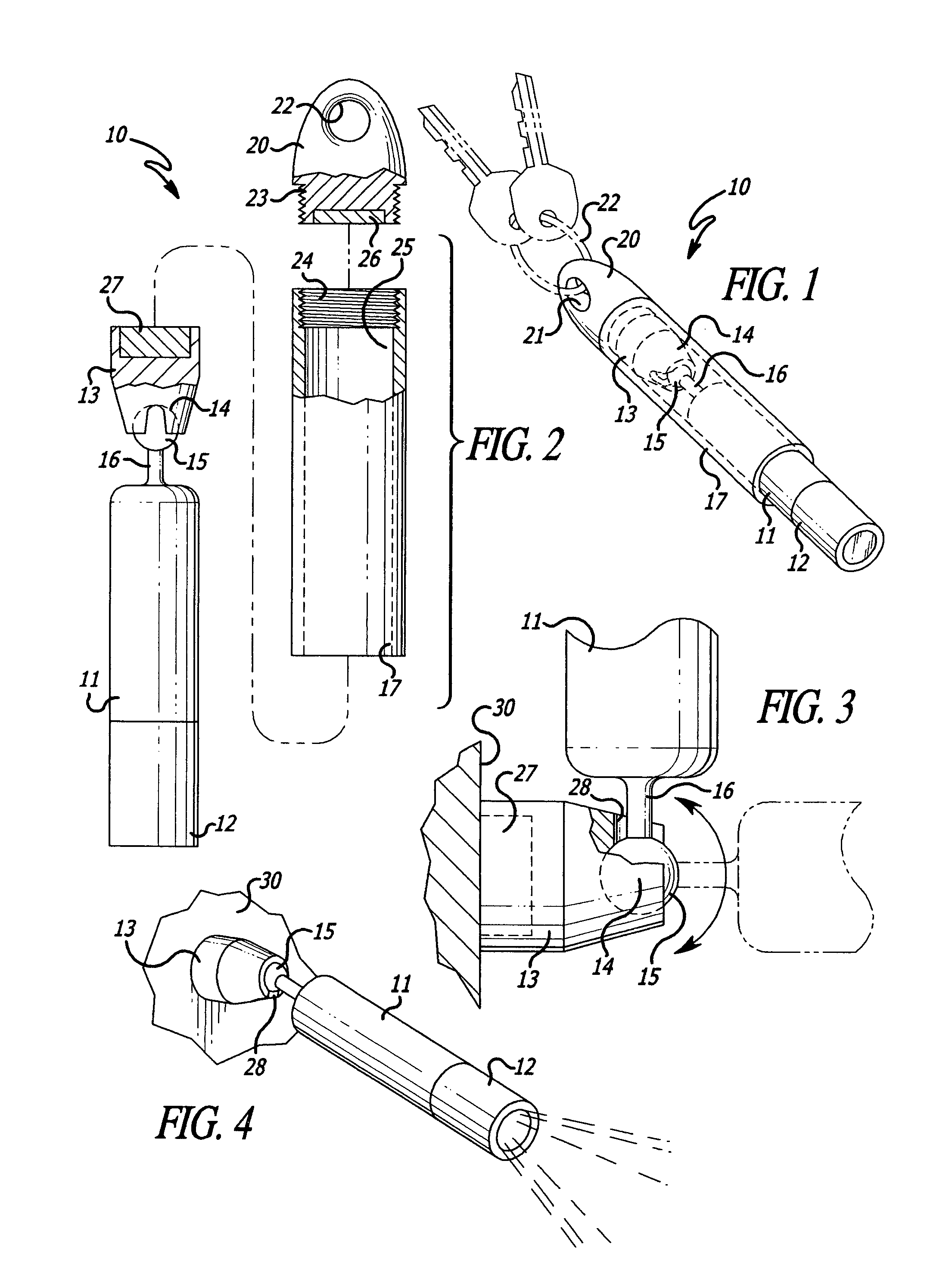
[0010]Therefore, it is among the primary objects of the present invention to provide a novel articulated light source with a magnetic base so that the light can be stored in a holding sleeve by magnetic force and when withdrawn from the holding sleeve, the magnetic means can mount the illumination means to an appropriate supporting structure.

Problems solved by technology

Such illumination means are generally bulky and, when in use, require that the illumination means be held in one hand permitting the person to use his or her other hand in the performance of the procedure.
Such a stand is separate from and independent of the illumination device itself and requires either permanent fixture to a wall, post or other support structure or the stand must be stored in a storage area until time for use, which takes up space and requires additional expense.
These problems and difficulties are due primarily to the fact that the illumination means or device does not incorporate an integral mount for supporting the illumination means or device from any one of a variety of available structures or portable holders, such as a wall surface, post, cartridge, or the like.
Also, conventional holders or supports for illumination means or devices are generally fixed in one position or require multiple components for movable mounts, which complicate not only structure construction and assembly but maintenance procedures as well.

Method used


Image

  • Articulated light
  • Articulated light
  • Articulated light

Examples


Embodiment Construction

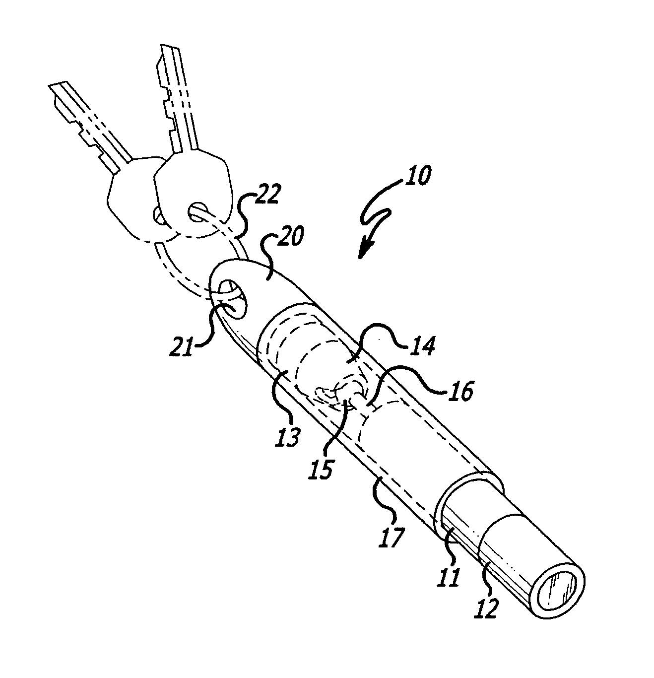
[0026]Referring to FIG. 1, the novel articulated illumination means incorporating the present invention is illustrated in the general direction of arrow 10 and the illumination means is in a first position, which may be referred to as a storage and / or a carrying position. The illumination means per se includes a housing or body 11 having a light source and battery 12 disposed on one end of the body, as shown in solid lines, and a support body or member 13 carried on the other end of the housing, and identified in broken lines. The member 13 is connected to the housing 11 by means of a universal joint comprising a socket 14 into which a ball 15 is mounted. The ball 15 is carried on the end of a shaft or shank 16 which is fixed to the end of housing 11.

[0027]It is to be particularly noted that the illumination means is in a carrying or storage position wherein the device is inserted into an open-ended bore formed in a sleeve holder 17. Secured to the end of sleeve holder 17 is a base ...


PUM


Abstract

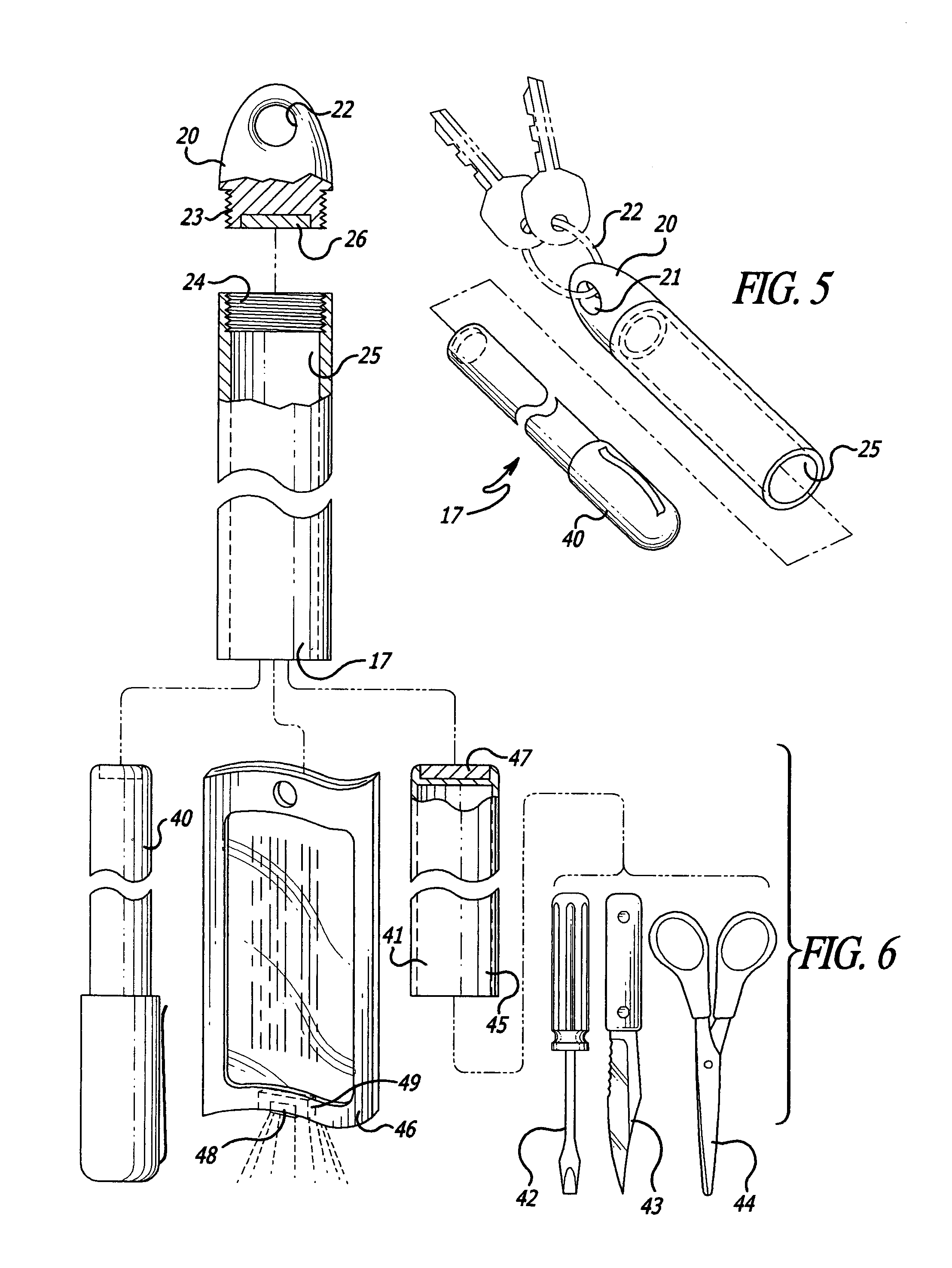
An articulated illumination device includes an elongated holding sleeve with one end threadably attached to a support body or base which communicates with an iron slug in an interior storage compartment for insertably receiving and magnetically holding the device. The storage compartment insertably receives a magnetic end of the illumination means that is releasably engageable with the iron slug and a battery-operated light is disposed at the other light or end. A universal joint includes a ball socket and joint formed in the support body or base for rotatably mounting a selected end of the illumination device. A magnet is intended to either attach to the support body or base by magnetic attraction to the iron slug when the illumination means is in the storage compartment or the magnet is employed for supporting the illumination means in a cantilevered position from a wall surface, a post or the like. The socket of the universal joint includes an open slot so that a shank carrying the ball permits the illumination means to rotate 90° from the longitudinal axis of the illumination means. A plurality of miniature accessory items may be carried in the holding sleeve when the illumination means has been withdrawn from the storage compartment. The holding sleeve may insertably receive and magnetically retain and store such items as a pen, tool kit, luggage tag or the like.

Description

[0001]Priority claimed on Ser. No. 60 / 407,801 filed Sep. 4, 2002.BACKGROUND OF THE INVENTION[0002]1. Field of the Invention[0003]The present invention relates to the field of portable illumination devices, and more particularly to a novel illuminating means having a light carried at one end and a support body member coupled to its opposite end by means of an universal joint, and which further includes a magnet, a suction cup, clip or the like on the support body for releasably securing the illuminating means to a supporting structure such as a pocket key ring, a holder cartridge, storage sleeve, wall surface, or the like.[0004]2. Brief Description of the Prior Art[0005]In the past, it has been the conventional practice for a person to employ a pocket light or flashlight to illuminate a specific area in order to visually observe an object or in the performance of conducting a particular procedure. Such illumination means are generally bulky and, when in use, require that the illumina...

Claims


Application Information

Patent Timeline
Patent Type & Authority Patents(United States)
IPC IPC(8): F21L4/00
CPCA44B15/005B25G1/08B43K23/001B43K25/00B43K31/00F21L4/04F21V21/0965F21V21/145B43K29/00F21V21/30
Inventor PADDEN, STEPHEN J.
Owner SOG SPECIALITY KNIVES & TOOLS
Learn More