
Triple bearing arrangement for cantilevered roll shafts

a three-bearing arrangement and cantilever roll technology, applied in the field of rolling mills, can solve the problems of shaft deflection becoming a problem, excessive length of shaft in comparison to its diameter, etc., and achieve the effect of increasing rigidity

Inactive Publication Date: 2005-11-01
PRIMETALS TECH USA
View PDF6 Cites 0 Cited by
  • Summary
  • Abstract
  • Description
  • Claims
  • Application Information

AI Technical Summary

Benefits of technology

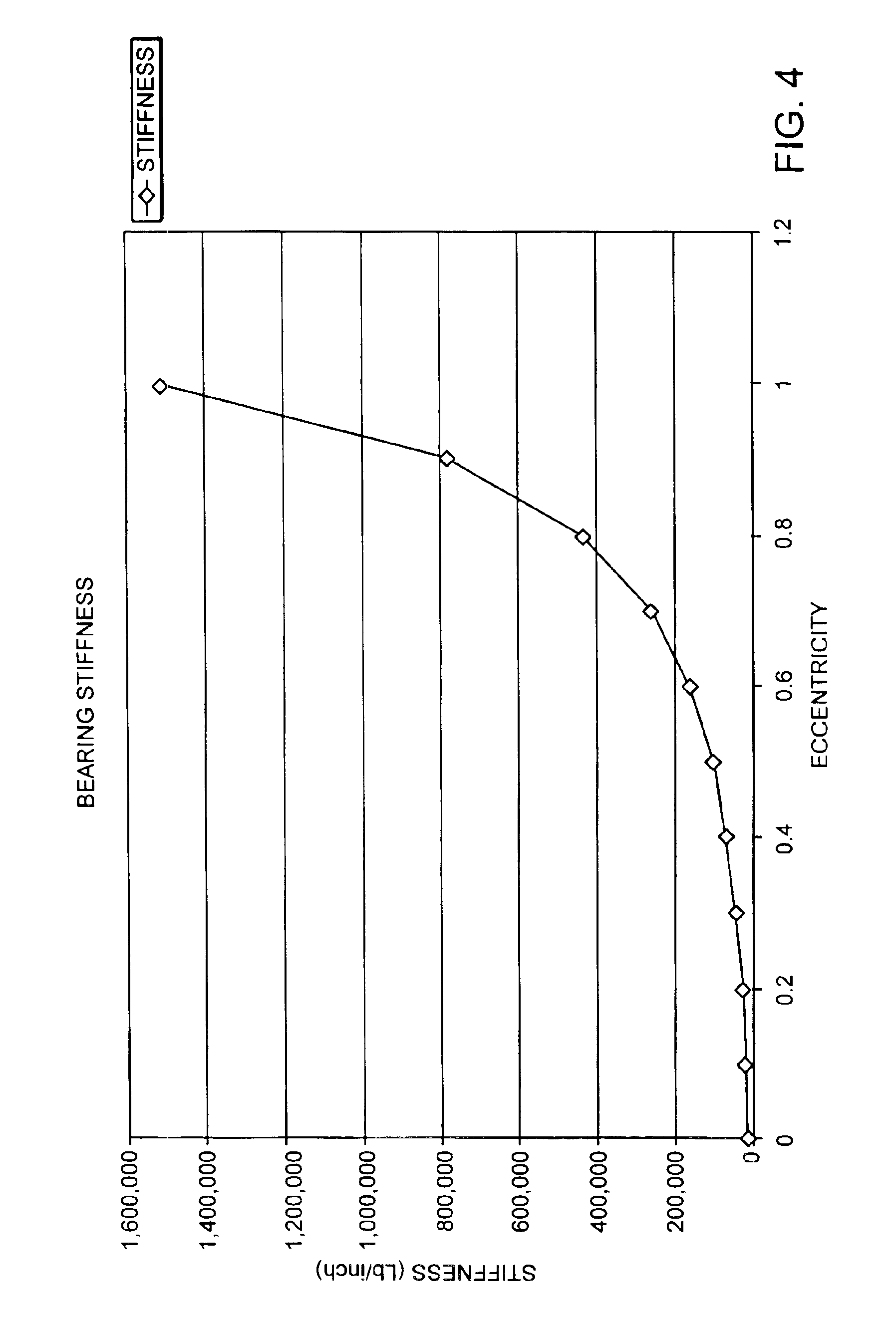
The present invention provides additional shaft rigidity by adding oil film type bearings between the conventional work and drive side bearings. These bearings have self-modulating stiffnesses that increase in direct proportion to bearing eccentricity, without the need for separately controlled hydrostatic introduction of pressurized oil. The third bearings are radially supported by both the eccentric sleeves and the cartridge housing, thus providing increased rigidity as compared to known prior art arrangements.

Problems solved by technology

With the advent of smaller diameter work rolls, roll shaft diameters are also of necessity decreased, resulting in shaft lengths being excessively long in comparison to their diameters.
Although the conventional two bearing arrangement can satisfy strength requirements reasonable well, the same is not true for stiffness, and shaft deflection becomes a problem.
In addition to being unduly complex and expensive, this arrangement suffers from a lack of rigidity in that the roll shafts are merely contained by the pressure sleeves, with the latter lacking critical radial support from the surrounding cartridge housing.

Method used


Image

  • Triple bearing arrangement for cantilevered roll shafts
  • Triple bearing arrangement for cantilevered roll shafts
  • Triple bearing arrangement for cantilevered roll shafts

Examples


Embodiment Construction

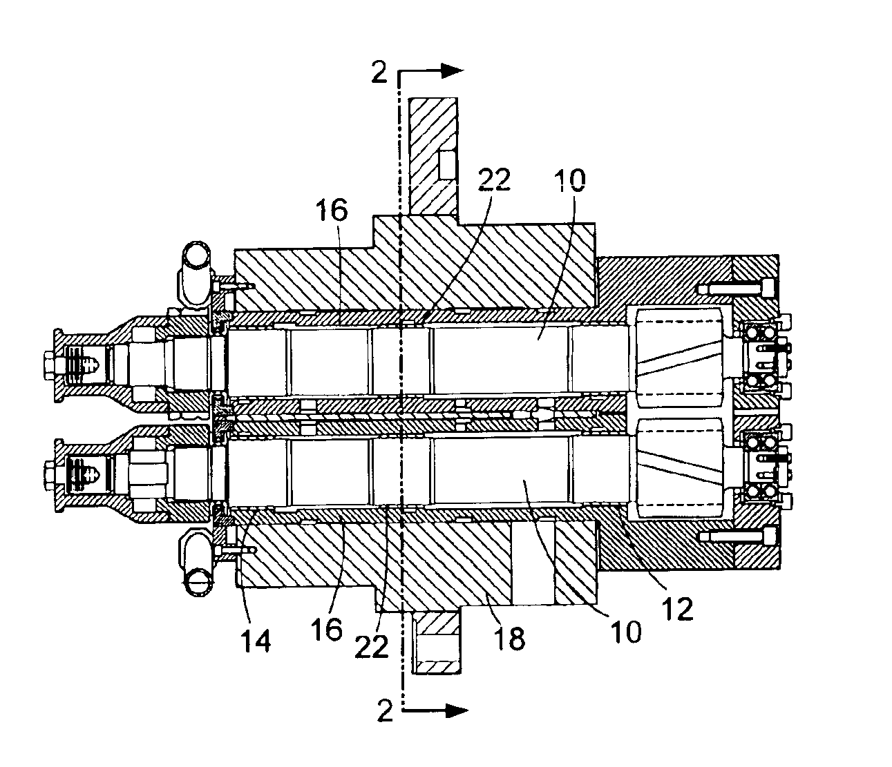
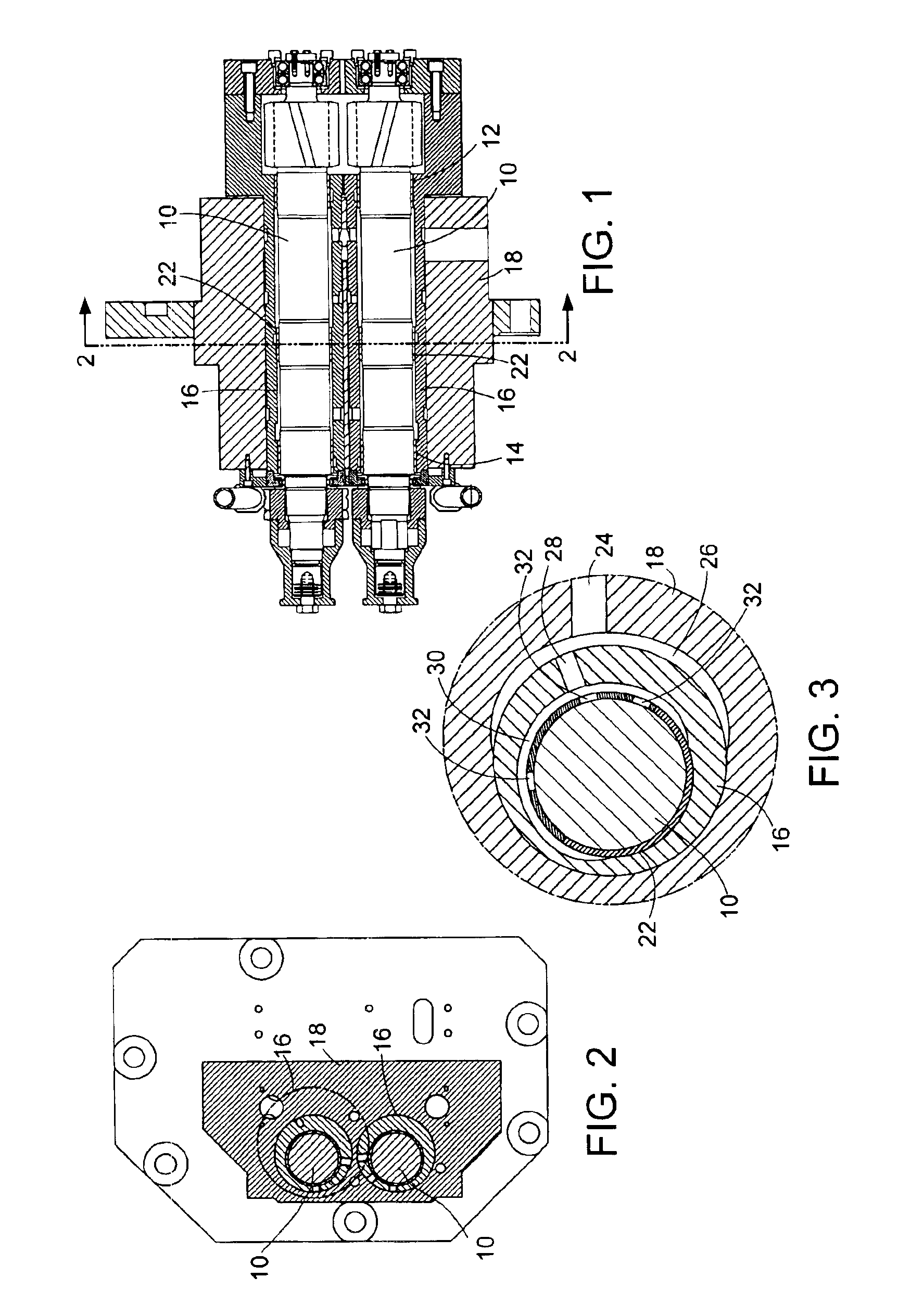
[0015]Referring initially to FIGS. 1 and 2, roll shafts 10 are rotatably supported by drive and work side sleeve bearings 12, 14 contained in eccentric sleeves 16. The eccentric sleeves are journalled for rotation and rotatably adjustable within a cartridge housing 18. The cantilevered outboard ends 10a of the roll shafts are configured to support work rolls (not shown), and the cantilevered inboard ends carry gears 20 configured and arranged to mesh with drive gears (not shown) of the mill drive.

[0016]The midsections of the roll shafts are journalled for rotation in third bearings 22 contained within midsections of the eccentric sleeves 16, with the midsections of the eccentric sleeves being tightly contained within and thus robustly backed by the cartridge housing. The bearings 22 are of the sleeve-type, lubricated by oil, with shaft rotation creating a hydrodynamic film of oil at the load zones of the bearings.

[0017]More particularly, and as can best be seen in FIG. 3, the cartri...


PUM

PropertyMeasurementUnit
stiffnessesaaaaaaaaaa
diameteraaaaaaaaaa
diametersaaaaaaaaaa

Abstract

A rolling mill roll stand comprises parallel roll shafts rotatably supported by axially spaced first and second bearings contained in parallel eccentric sleeves. The eccentric sleeves are rotatably supported in a housing and the roll shafts have cantilevered ends that project externally from one side of the housing and that are adapted to carry work rolls. Third oil film bearings are contained by the eccentric sleeves and are arranged to rotatably support the roll shafts at intermediate locations between and spaced axially from both the first and second bearings.

Description

CROSS REFERENCE TO RELATED APPLICATION[0001]This application claims priority from Provisional Application Ser. No. 60 / 468,807 filed May 8, 2003.BACKGROUND OF THE INVENTION[0002]1. Field of the Invention[0003]This invention relates generally to rolling mills for rolling long products, e.g., rods, bars and the like, and is concerned in particular with an improvement to the so-called “cantilevered” roll stands, where the work rolls are mounted on the distal ends of support shafts.[0004]2. Description of the Prior Art[0005]Cantilevered work rolls are conventionally mounted on the distal ends of parallel support shafts. The shafts are journalled for rotation in axially spaced work and drive side bearings contained in eccentric sleeves, the latter in turn being mounted for rotatable adjustment in a cartridge housing. The roll shafts carry gears arranged to mesh with gears of the mill drive, and by simultaneously rotating the eccentric sleeves in opposite directions, symmetrical adjustment...

Claims


Application Information

Patent Timeline
Patent Type & Authority Patents(United States)
IPC IPC(8): B21B31/07B21B31/00B21B31/16B21B31/26B21B1/16B21B13/00B21B31/20
CPCB21B31/07B21B1/16B21B13/005B21B31/074B21B31/26H04M1/026H04M1/23B32B27/06
Inventor TITUS, DAVID G.
Owner PRIMETALS TECH USA
Learn More