
Conformal transverse hat profile roller

a transverse hat and profile technology, applied in the field of uniformity, can solve the problems of long cycle time of several days, compromising the objectives of preform preparation, and affecting the final preparation of the preform

Inactive Publication Date: 2005-09-13
NORTHROP GRUMMAN SYST CORP
View PDF26 Cites 43 Cited by
  • Summary
  • Abstract
  • Description
  • Claims
  • Application Information

AI Technical Summary

Benefits of technology

The present invention provides a variable pressure roller system for installing a preform onto a mold surface by applying pressure. The system includes a roller carriage with a grasping handle and a plurality of rollers. Each roller is designed to generate a specific pressure and is removably engageable with the roller carriage. The rollers are made of a metallic material and may be fabricated from aluminum or steel. The system also includes an elongated shaft with a plurality of rollers engageable therein. The rollers may have a recess to move along the pyramidal configuration of the mold surface. The system may also include at least one ply, a peel ply, a film, and a fillet to receive the pressure and conform the preform to the mold surface. The technical effect of the invention is to provide a reliable and efficient method for installing a preform onto a mold surface with uniform pressure distribution.

Problems solved by technology

However, in this process, resin is simultaneously drawn in through an inlet port in the vacuum bag and through the lay-up impregnating it.
The initial preparations needed for the preforms to be subsequently cured frequently involve manual labor.
In the industry that values time-efficiency, precision and cost-effectiveness, the current preparations of preforms may oftentimes compromise such objectives.
Such method may result in long cycle times of several days.
Furthermore, due to the lengthy cycle time, the profits in a given project that utilizes such method may be reduced from its projected optimal range.
More importantly, however, the lay-up of the preform upon the mold may be inappropriately accomplished because the manual approach of the current method lacks systematic uniformity, and thus compromising the requisite precision at times. Therefore, in the industry where such composite parts are often mass-produced, the inapt preparations just described may prove to have undesired effects upon the overall manufacturing of the composite parts.

Method used


Image

  • Conformal transverse hat profile roller
  • Conformal transverse hat profile roller
  • Conformal transverse hat profile roller

Examples


Embodiment Construction

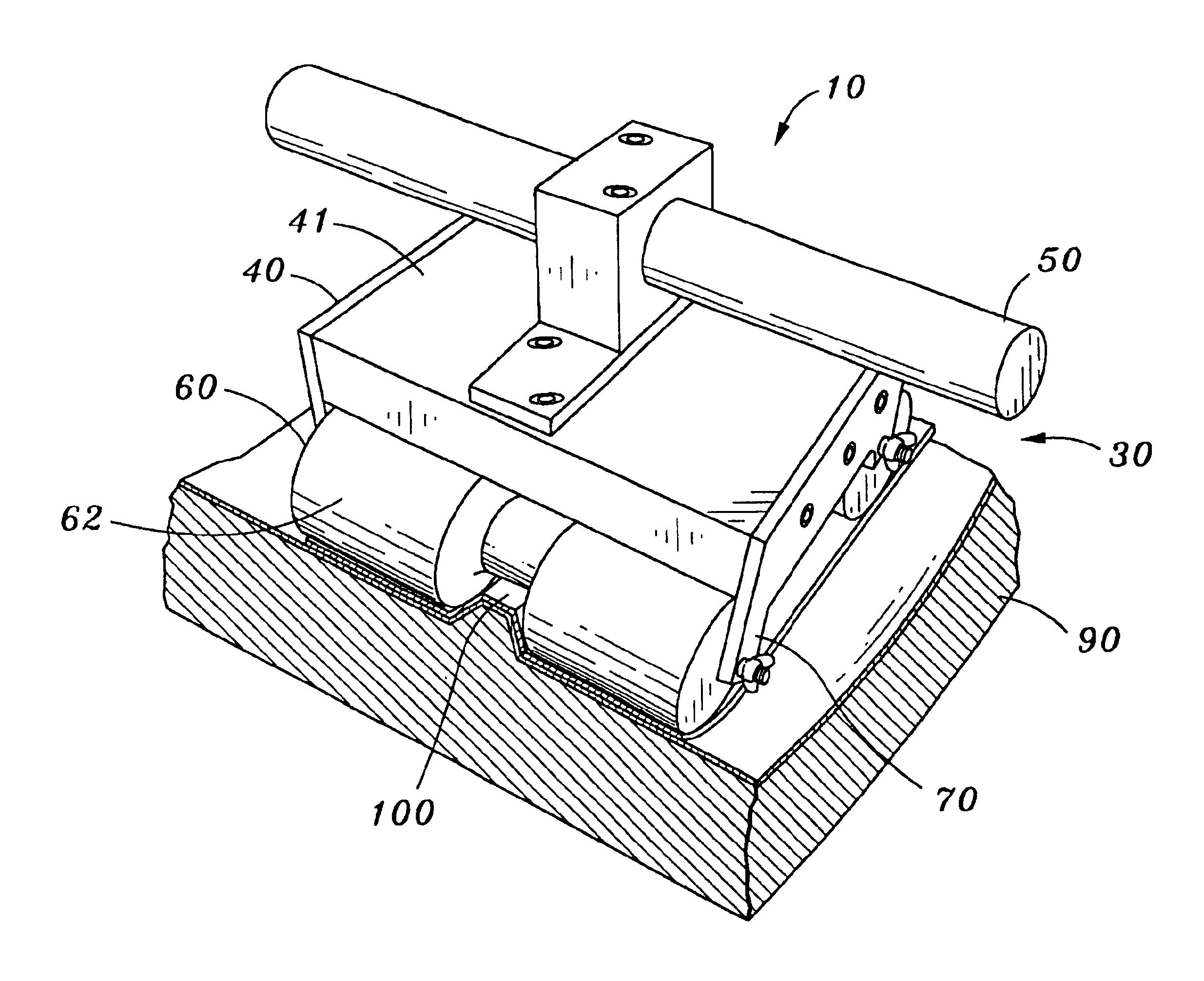
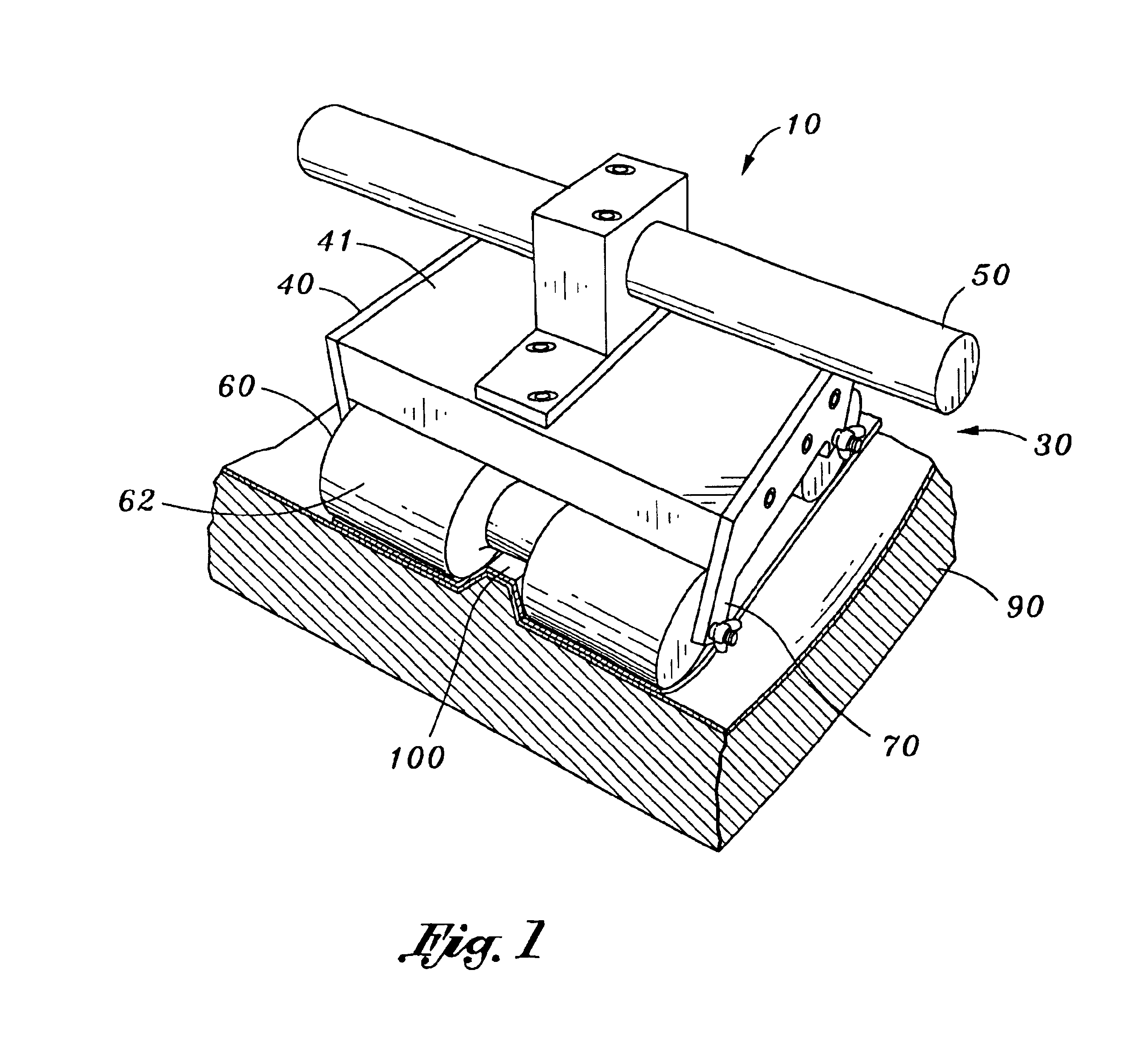
[0030]Referring now to the drawings wherein the showings are for purposes of illustrating preferred embodiments of the present invention only, and not for purposes of limiting the same, FIG. 1 perspectively illustrates a roller system 10 constructed in accordance with a preferred embodiment of the present invention. The roller system 10 is adapted to be utilized for installing a preform 20 onto a mold surface 30 by applying pressure thereon. In this regard, the roller system 10 may be formed to have a variety of shapes, configurations, and geometries to achieve such purpose, namely, applying the pressure on the mold surface 30 having the preform 20 laid thereupon.

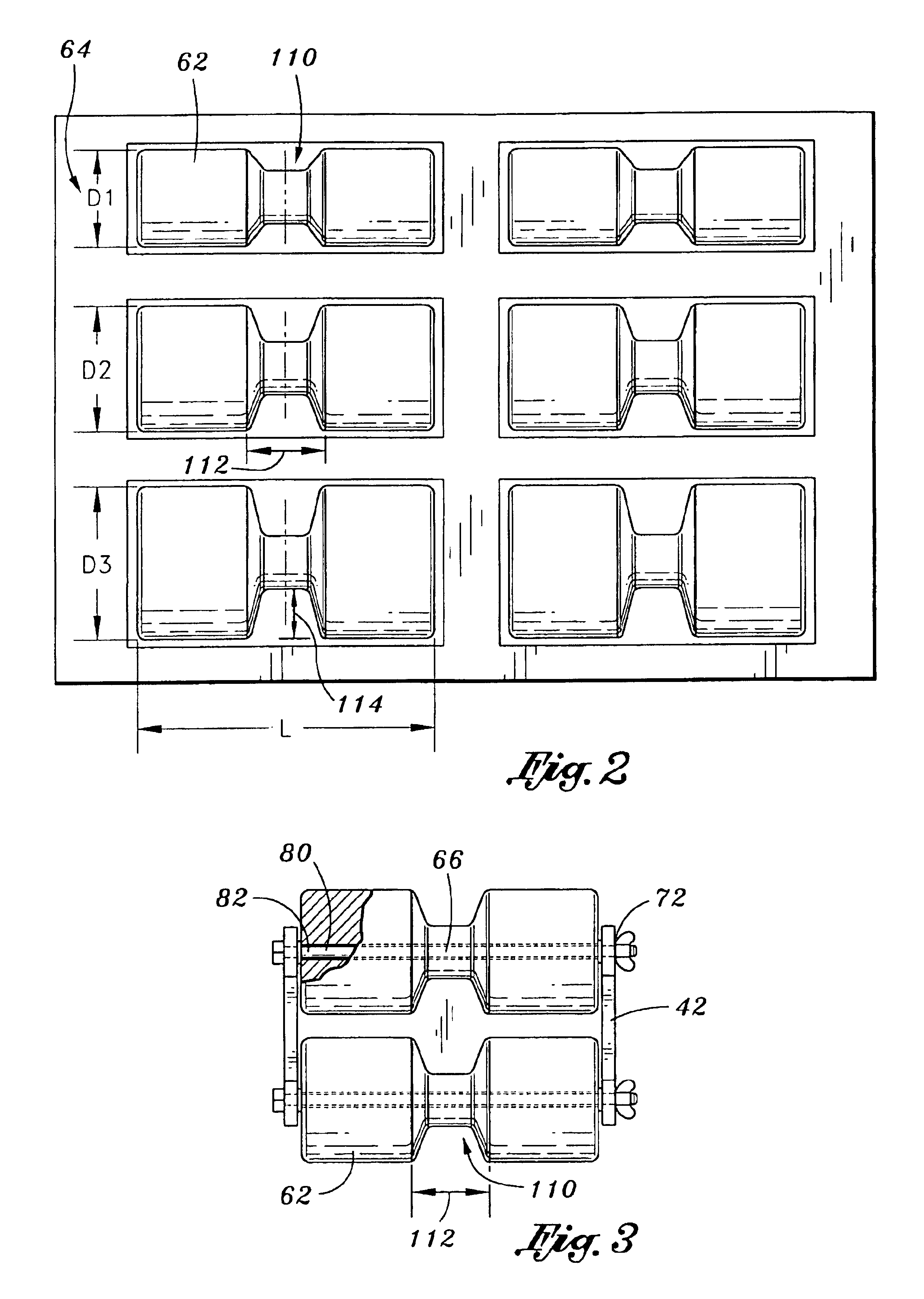
[0031]Referring now to FIGS. 1 and 2, as the roller system 10 may be any general shape, it is understood that the roller system 10 as depicted is symbolic in nature, and it is the concept of utilizing such system 10 that should be appreciated. The roller system 10 primarily comprises a roller carriage 40, a grasping handle ...


PUM

PropertyMeasurementUnit
temperatureaaaaaaaaaa
pressureaaaaaaaaaa
weightaaaaaaaaaa

Abstract

There is provided a variable pressure roller system for installing a preform having contact surfaces onto a configuration of a mold surface by applying pressure thereon. The roller system of the present invention comprises a roller carriage. A grasping handle may be mounted to the roller carriage. Moreover, the roller system may further comprise a plurality of rollers, wherein each respective one of the plurality of rollers is defined by a weight to generate a specific pressure corresponding thereto. Furthermore, each respective one of the plurality of rollers may be removably engageable to the roller carriage. Each respective one of the plurality of rollers may be adapted to uniformly distribute the specific pressure corresponding thereto on the contact surfaces for conforming the preform to the configuration of the mold surface when engaged to the roller carriage.

Description

CROSS-REFERENCE TO RELATED APPLICATIONS[0001](Not Applicable)STATEMENTS RE: FEDERALLY SPONSORED RESEARCH / DEVELOPMENT[0002](Not Applicable)BACKGROUND OF THE INVENTION[0003]The present invention generally relates to an apparatus and a method for installing a preform onto a mold surface, and more particularly to an improved apparatus and method for installing a preform onto a contoured mold surface via a roller device having a selectable roller skate to apply pressure thereon.[0004]The installation of preforms onto a specified mold surface to form composite materials is well known in commercial and military applications. The resulting composite materials are desirable due to their mechanical characteristics such as a high strength to weight ratio and high thermal tolerances. As such, the preforms and the corresponding mold surfaces are essential initial components in the resulting composite materials that are frequently used to build structural supports, such as ducts for aircrafts.[00...

Claims


Application Information

Patent Timeline
Patent Type & Authority Patents(United States)
IPC IPC(8): B23P17/00
CPCB29C70/342B29C70/388Y10T29/4517Y10T29/53909Y10T156/18Y10T29/49812
Inventor MEAD, WILLIAM T.POTTER, JOHNGONZALES, NARCISO
Owner NORTHROP GRUMMAN SYST CORP
Learn More