
Liquid crystal display apparatus

a liquid crystal display and display device technology, applied in static indicating devices, instruments, cathode-ray tube indicators, etc., can solve the problems of liquid crystal property deterioration, motion image blurring, and slight reduction of contrast, so as to achieve optimal display of motion and still images, uniform luminance

Inactive Publication Date: 2005-09-06
PANASONIC LIQUID CRYSTAL DISPLAY CO LTD +1
View PDF14 Cites 34 Cited by
  • Summary
  • Abstract
  • Description
  • Claims
  • Application Information

AI Technical Summary

Benefits of technology

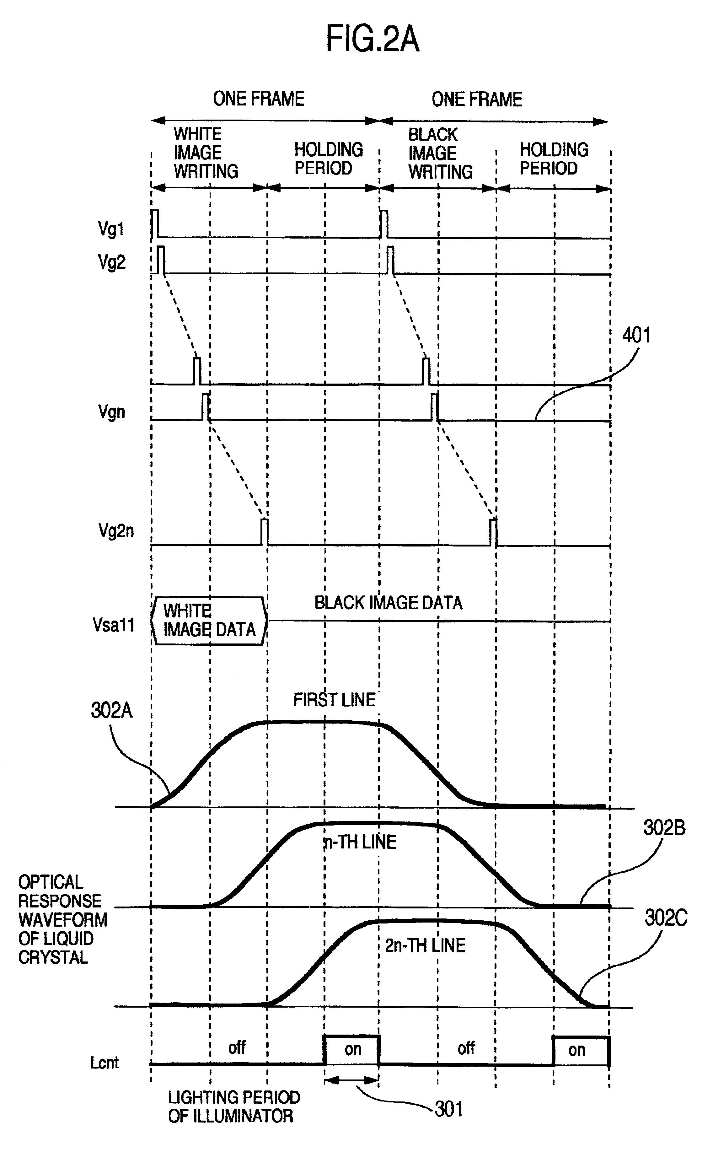
"The present invention provides a liquid crystal display apparatus that can display high-definition motion images without any residual images, flickers, crosstalk, or blurring. The apparatus uses intermittent lighting of an illuminator and application of a preset voltage in combination. The apparatus also has higher luminance towards the center of the screen and no luminance differences in the boundary of scanning. The driving method includes a sequence of writing and holding periods, and the apparatus is scanned from one line or a pair of adjacent lines to the entire screen in both upper and lower directions. The invention also provides an illuminator that can make uniform luminance on the screen and a method for optimally displaying motion and still images by switching the illuminator between the two types of images."

Problems solved by technology

However, in the case of a high-speed motion image, in which an object quickly moves, for example a sports program, image blurring, a contrast reduction slightly lowering image definition, and other problems occur.
In such a conventional liquid crystal display apparatus, a cause of motion image blurring is considered to be a combination of a liquid crystal response speed and hold displaying common to the liquid crystal display apparatus and a plasma display apparatus.
It is generally known that liquid crystal property is deteriorated when a DC voltage is applied.
But the liquid crystal optical response is not sufficiently completed in pixels of lines lower than the n-th.
However, in a current liquid crystal display apparatus, an optical response time of a liquid crystal often exceeds even 20 ms.
Consequently, it is difficult to suppress occurrence of flickers caused by superimposition of a DV voltage, and to achieve displaying of a motion image without any residual images.
In this case, however, a certain writing operation is carried out during intermittent lighting of the illuminator, unfavorable crosstalk may be generated through a parasitic capacity between the line or column wiring and the pixel.

Method used


Image

  • Liquid crystal display apparatus
  • Liquid crystal display apparatus
  • Liquid crystal display apparatus

Examples


first embodiment

[0064

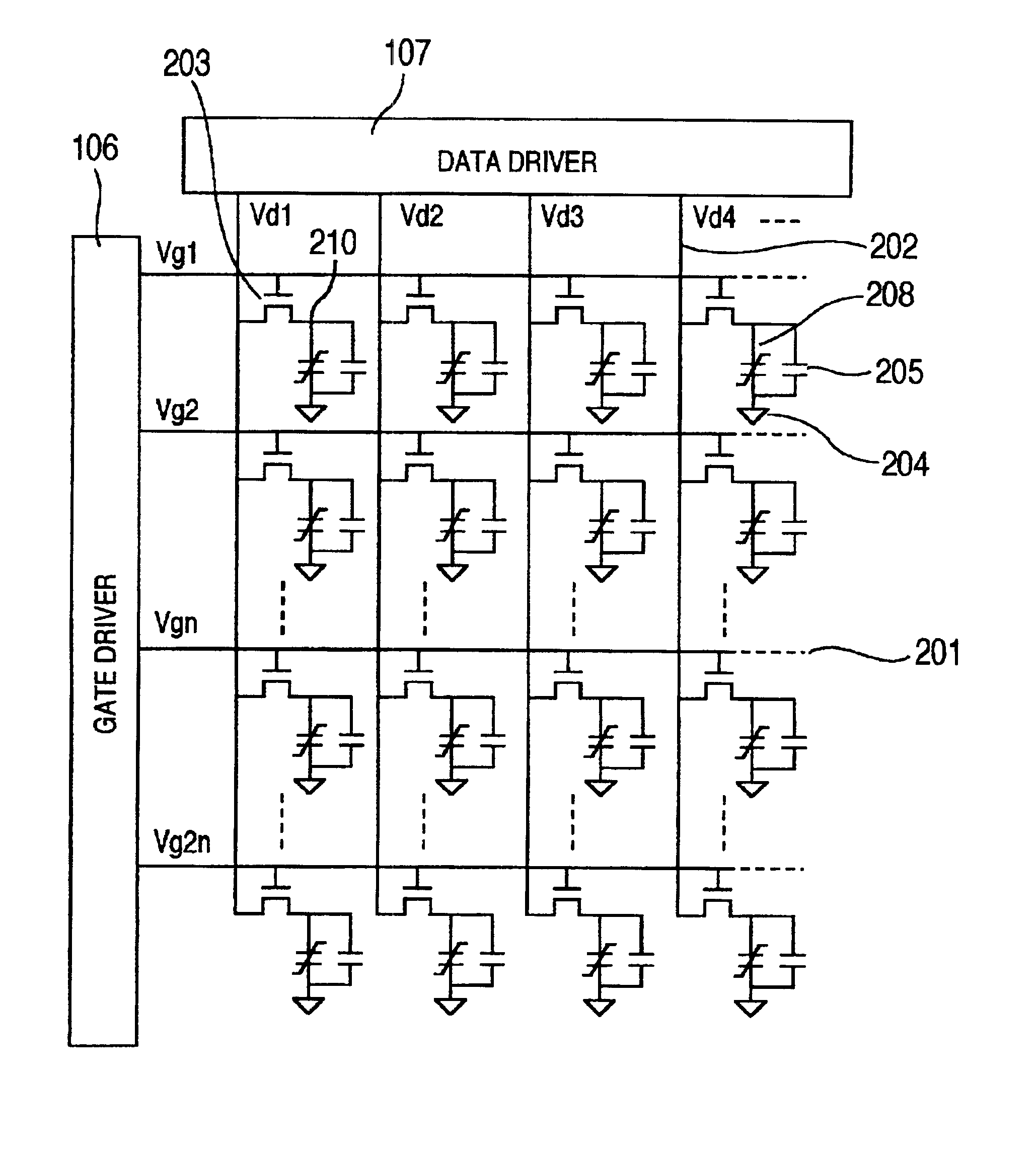
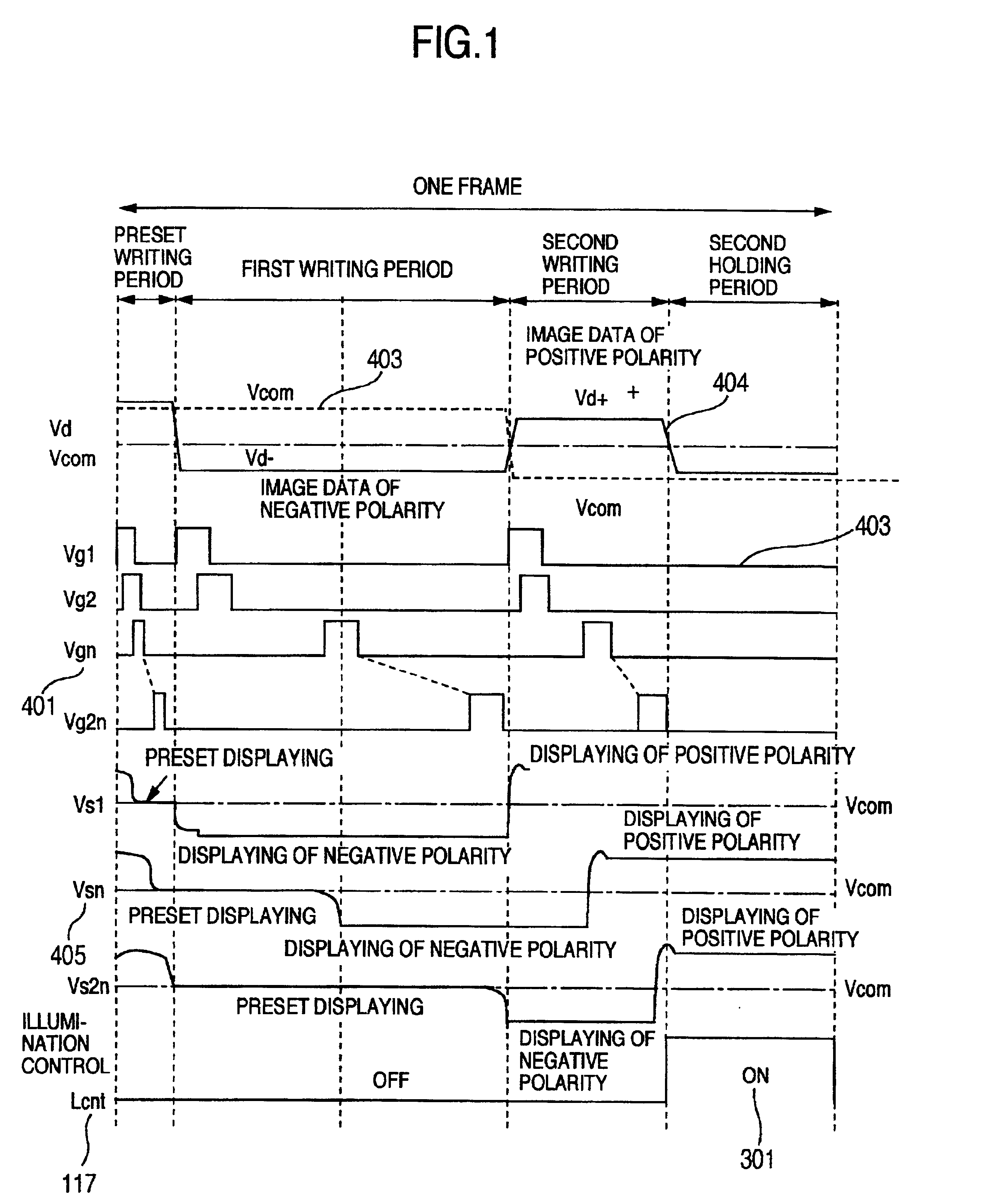
[0065]Now, the first embodiment of the invention is described by referring to FIG. 1, and FIGS. 5 to 8, by way of example where a driving system of the invention is applied to a normally black in-plane switching mode for realizing black displaying when no voltage is applied, i.e., a voltage equal to / lower than a threshold value is applied. The embodiment is described by taking the example of the in-plane switching mode. However, it should be understood that the embodiment can be applied widely to liquid crystal display apparatus using an illumination optical system of TN and MVA modes or a projection type. FIG. 1 shows a driving sequence according to the first embodiment of the invention; FIG. 5 an equivalent circuit in a display unit of the liquid crystal display apparatus; FIG. 6 a comparative view of response characteristics in transfer to black displaying between presence and nonpresence of preset driving; FIG. 7 a system configuration view showing an entire configuration a...

second embodiment

[0081

[0082]Next, description is made of a second embodiment of the present invention by referring to FIG. 9. This embodiment is applied to a normally black in-plane switching mode as in the case of the first embodiment. The invention provides a display driving system suitable for interlaced driving generally used for broadcast image data or stored motion image data, and maintaining image definition high, and a display apparatus. FIG. 9 shows a driving sequence of main portions of the embodiment. A basic driving sequence is similar to that of the first embodiment. However, a method of transferring image data to the liquid crystal display apparatus corresponding to interlaced data, and a panel driving method according to this are different.

[0083]Display image data constructed based on interlaced driving specifications includes an odd field composed of image data of odd lines, and an even field composed of image data of even lines. When these interlaced image data are applied to a disp...

third embodiment

[0085

[0086]Next, description is made of a third embodiment of the present invention by referring to FIGS. 10A and 10B, 11 and 27A and 27B, and FIGS. 28A to 34. As in the case of the first embodiment of the invention, the embodiment is applied to a normally black n-plane switching mode. The invention provides a liquid crystal display apparatus capable of controlling brightness of a motion image, and suppressing longitudinal smear or crosstalk. The embodiment can also be applied to a display mode, in which a common wiring and a common electrode can be provided on the same substrate, a display mode, in which a common wring and a common electrode are provided on opposing substrates, and a display mode, in which circuits capable of individually controlling common writings are provided on opposing substrates. Each of FIGS. 10A and 10B shows an equivalent circuit in a display unit of the liquid crystal display apparatus of the embodiment; FIG. 11 a driving sequence of the embodiment; FIGS....


PUM

PropertyMeasurementUnit
frame frequencyaaaaaaaaaa
frequencyaaaaaaaaaa
timeaaaaaaaaaa

Abstract

A liquid crystal display apparatus which is adapted to divide one frame period into a preset writing period, a first writing period, a first holding period, a second writing period, and a second holding period, to be driven in this sequence. The first and second writing periods have reverse writing voltage polarities and the second writing period is set to be about ½ of the first writing period.

Description

BACKGROUND OF THE INVENTION[0001]1. Field of the Invention[0002]The present invention relates to a liquid crystal display apparatus and, more particularly, to a liquid crystal display apparatus suitably used for motion image displaying, and a method for driving the same.[0003]2. Description of the Related Art[0004]The liquid crystal display apparatus have widely been used as display units for mobile devices represented by desktop and notebook type personal computers, a portable telephone set and the like. Recently, with increased demands for smaller market space and lower consumption of power, attention has been focused on liquid crystal television as a replacement for a cathode ray tube (CRT). Compared with the display unit such as the CRT, the liquid crystal display apparatus exhibits more excellent performance including reductions in size, weight and consumption of power, an increase in definition and the like. In the case of a low-speed motion image, in which an object to be dis...

Claims


Application Information

Patent Timeline
Patent Type & Authority Patents(United States)
IPC IPC(8): G09G3/36G09G3/20G02F1/133G09G3/34G09G5/399
CPCG09G3/3648G09G3/3614G09G3/3666G09G5/399G09G2300/0434G09G2300/0809G09G2310/0205G09G2310/021G09G2310/0251G09G2310/062G09G2320/0209G09G2320/0261G09G2320/103
Inventor KONNO, AKITOYOTSUMURA, MAKOTOYAMAMOTO, TSUNENORIHIYAMA, IKUOAONO, YOSHINORI
Owner PANASONIC LIQUID CRYSTAL DISPLAY CO LTD
Learn More