Apparatus for carrying golf clubs

a golf club and apparatus technology, applied in the field of golf clubs, can solve the problems of difficult replacement of such a used partition with a new one, easy wear and tear of the upper portion of the golf club 60,

Inactive Publication Date: 2005-09-06
CHENTERLON
View PDF7 Cites 6 Cited by
  • Summary
  • Abstract
  • Description
  • Claims
  • Application Information

AI Technical Summary

Problems solved by technology

However, the golf clubs 60 easily wear out the upper portions of the partitions 74 and 76.
It is difficult to replace such a used partition with a new one.

Method used


Image

  • Apparatus for carrying golf clubs
  • Apparatus for carrying golf clubs
  • Apparatus for carrying golf clubs

Examples


Embodiment Construction

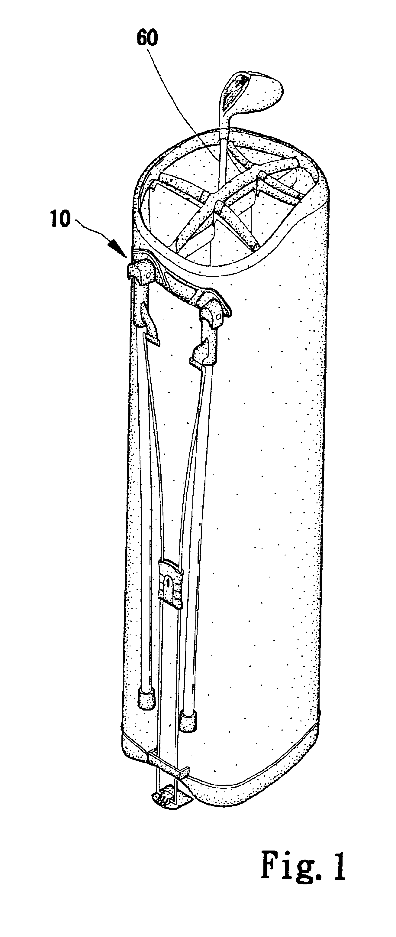
[0014]Referring to FIG. 1, a golf club 60 is put in a club-carrying apparatus 10 according to the preferred embodiment of the present invention.

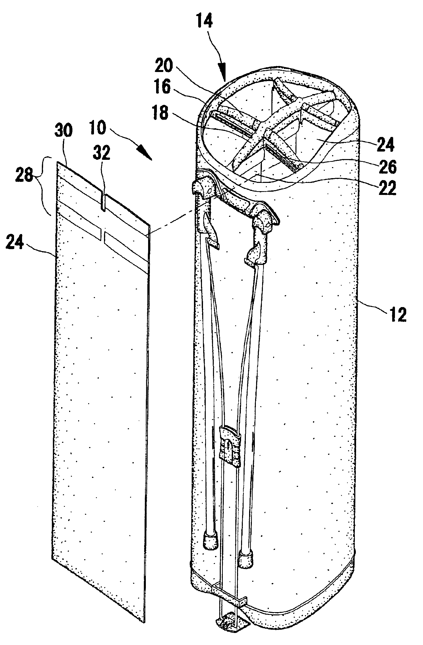
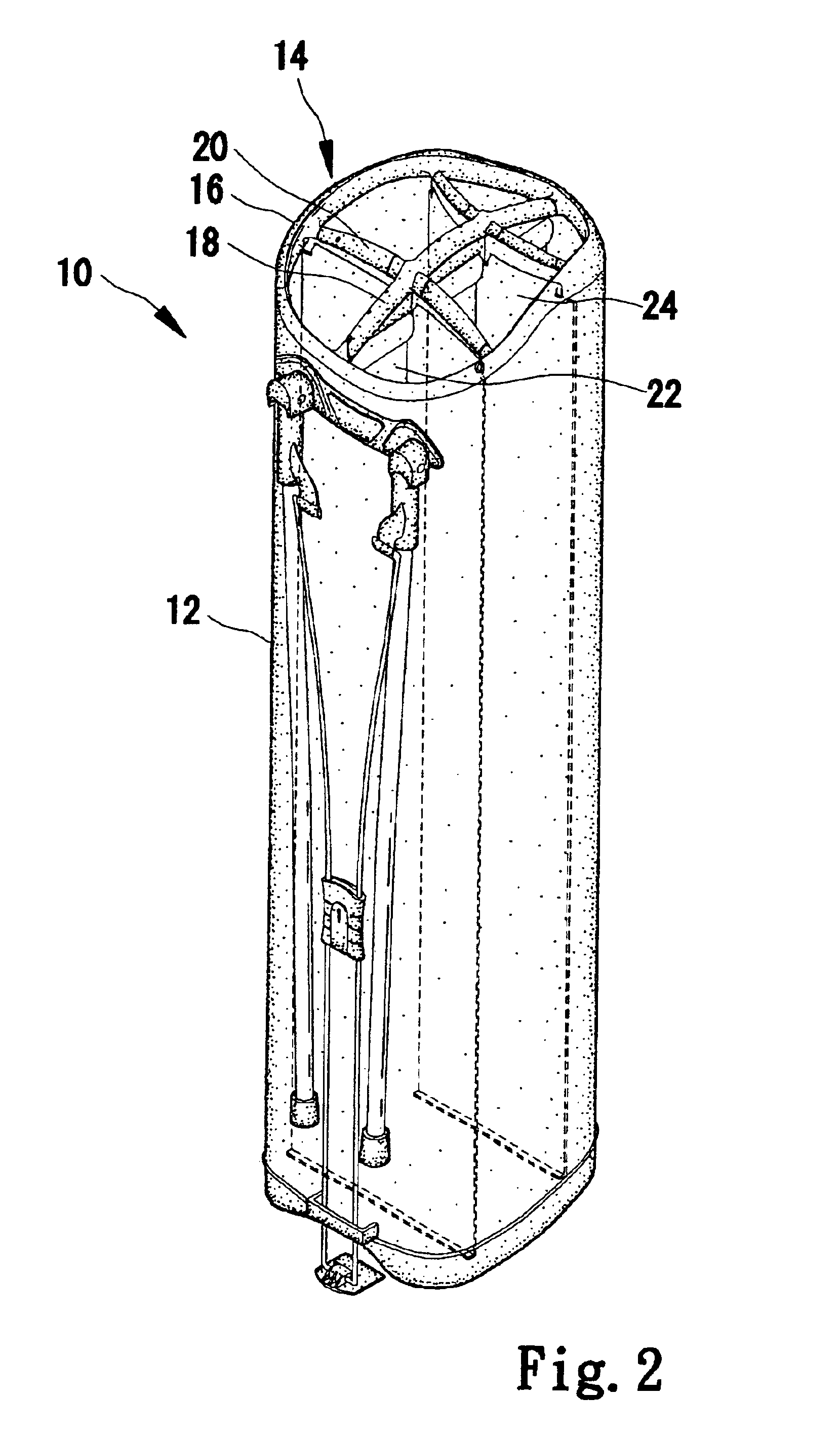
[0015]Referring to FIG. 2, the club-carrying apparatus 10 includes a bag 12 and a frame 14 attached to an upper portion of the bag 12. The frame 14 includes an annular element 16, a sternum-like element 18 and two rib-like elements 20 intersecting the sternum-like element 18. The sternum-like element 18 is divided into three sections by the rib-like elements 20. The annular element 16 provides rigidity to the bag 12. The sternum-like element 18 and the rib-like elements 20 separate golf clubs such as the golf club 60 from each other.

[0016]To separate the golf clubs, three partitions 22 and two partitions 24 are used. Each of the partitions 22 includes a lower portion attached to a bottom of the bag 12 and an upper portion attached to one of the sections of the sternum-like element 18. Each of the partitions 24 includes a lower portion attach...


PUM


Abstract

A club-carrying apparatus includes a bag and a frame. The frame includes an annular element, a sternum-like element and at least one rib-like element. The annular element is attached to an upper portion of the bag. The sternum-like element extends from the annular element and includes a bone and a skin covering the bone. The rib-like element intersects the sternum-like element and includes a bone and a skin covering the bone. Each of two partitions includes a lower portion attached to the bag and an upper portion attached to the bone of the sternum-like element. Another partition includes a lower portion attached to the bag and an upper portion attached to the bone of the rib-like element.

Description

FIELD OF INVENTION[0001]The present invention relates to a club-carrying apparatus.BACKGROUND OF INVENTION[0002]Referring to FIG. 5, a golf club 60 is inserted in a conventional club-carrying apparatus 62. The club-carrying apparatus 62 includes a bag 64 and a frame 66 attached to an upper portion of the bag 64. Referring to FIG. 6, the frame 66 includes an annular element 68, a sternum-like element 70 and three rib-like elements 72 (only two are shown). The annular element 68 provides rigidity to the bag 64. The sternum-like element 70 and the rib-like elements 72 separate golf clubs such as the golf club 60. The sternum-like element 70 is divided into three sections by the rib-like elements 72. A partition 74 includes an upper portion wrapping and holding to each section of the sternum-like element 70 and a lower portion attached to the bottom of the bag 64 via sewing, adhesion or any other proper manners. A partition 76 includes an upper portion wrapping and holding to each rib-l...

Claims


Application Information

Patent Timeline
Patent Type & Authority Patents(United States)
IPC IPC(8): A63B55/00A63B55/04
CPCA63B55/045A63B55/53A63B55/40
Inventor CHEN, CHANGFU
Owner CHENTERLON
Why Eureka
Try Eureka