Radio card having independent antenna interface supporting antenna diversity

a radio card and antenna diversity technology, applied in the field of computer devices, can solve the problems of severe limitation of the type of device that can accommodate the card, device inability to accommodate the extra length, and significant limitations of options

Inactive Publication Date: 2005-08-09
AVAGO TECH WIRELESS IP SINGAPORE PTE
View PDF39 Cites 27 Cited by
  • Summary
  • Abstract
  • Description
  • Claims
  • Application Information

AI Technical Summary

Benefits of technology

[0012]A first embodiment of the invention is useful in an electronic device having a device housing, a track for engagingly receiving a radio card, a first interface and a first antenna. In such an environment, the radio card comprises a card housing and a second interface, disposed on the card housing, that, upon receipt of the radio card by the electronic device, engagingly couples with the first interface. A radio circuit is disposed within the card housing and is communicatively coupled to the second interface. A third interface is electrically and physically independent of the second interface and is disposed on the card housing. The third interface is communicatively coupled to the radio circuit, and the third interface is engagingly coupled with the first antenna upon receipt of the radio card by the electronic device via the...

Problems solved by technology

These options have significant limitation.
Both connections severely limit the type of device that can accommodate the cards.
Most devices cannot accommodate the extra length without some modification and both connections make environmentally sealing the connections difficult Additionally, both connections are susceptible to increased damage from dropping or other physical trauma.
An external antenna to which the user must couple an antenna is inconvenient and subjects the radio periods of unreliability due to wear of the cable and connection.
An additional problem is converting computer devices that were not designed to utilize radio or modem cards, and thus have no built in or attached antenna, into devices that can utilize radio and modem cards while still avoiding the various antenna connection problems discussed above.

Method used


Image

  • Radio card having independent antenna interface supporting antenna diversity
  • Radio card having independent antenna interface supporting antenna diversity
  • Radio card having independent antenna interface supporting antenna diversity

Examples


Embodiment Construction

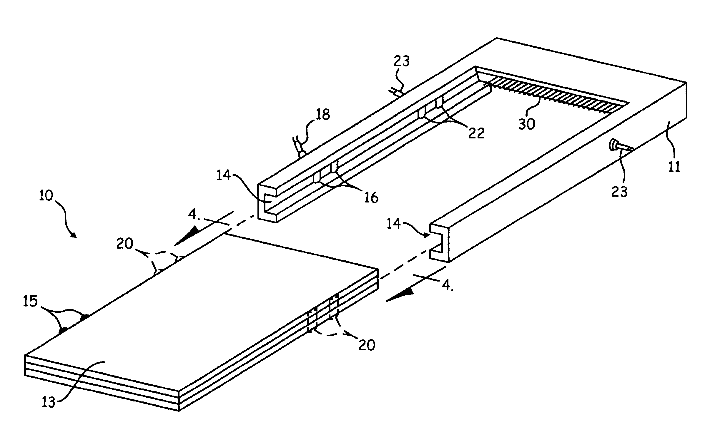
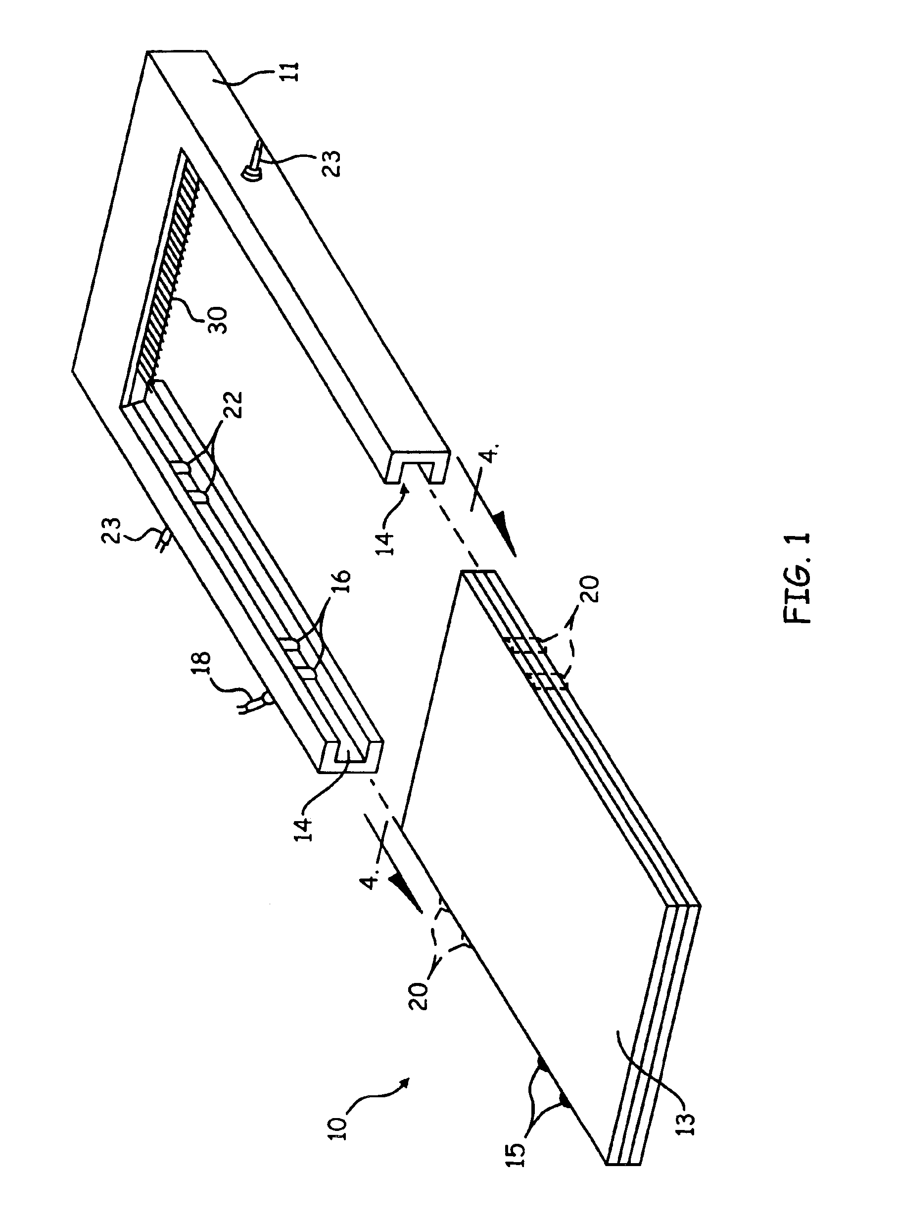
[0046]Referring now to the drawings wherein like reference numerals designate identical or corresponding parts throughout the several views, FIG. 1 shows a radio card (10) and a receiving device (11) built in accordance with the present invention. The radio card (10) has a housing (13) inside which is a completely operation radio transceiver (not shown). The receiving device (11) in this embodiment of the present invention uses a pair of opposed slots (14) to receive and guide the incoming radio card (10).

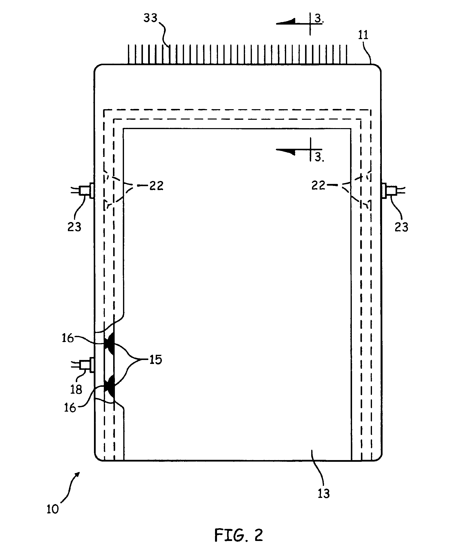
[0047]The radio card (10) has a pair of antenna contacts (15) positioned along the edge of the housing (13). The receiving device (11) has a corresponding pair of antenna contacts (16). As can be seen in. FIG. 2, when the radio card (10) is fully inserted into the receiving device (11) the antenna contacts (15) on the radio card housing (13) electrically encounter the corresponding set of antenna contacts (16) positioned on the receiving device (11). The antenna contacts (16) on th...


PUM


Abstract

A radio card, such as a PCMCIA card, received by an electronic device has a first interface coupling radio circuitry within the radio card to the electronic device. The radio card also has a second interface, independent of the first interface, that couples with an antenna disposed within the electronic device upon receipt of the radio card by the electronic device. The second interface may comprise a plurality of antenna contacts located along tracks of the electronic device used to aid reception of the radio card. A second and possibly external antenna may also automatically couple with the second interface upon insertion. By selective placement of the antenna contacts on the radio card, a specific one of the antennas may be selected. Otherwise, internal switching circuitry supports antenna diversity or simultaneous use of a plurality of antennas.

Description

CROSS REFERENCE TO RELATED APPLICATIONS[0001]This application is a continuation of U.S. application Ser. No. 08 / 960,194, filed Oct. 29, 1997, now abandoned which is a continuation of U.S. application Ser. No. 08 / 431,077, filed Apr. 27, 1995, now abandoned which is a continuation-in-part of U.S. application Ser. No. 08 / 401,526, filed Mar. 10, 1995, now abandoned which is in turn a continuation-in-part of U.S. application Ser. No. 08 / 258,285, filed Jun. 10, 1994, now U.S. Pat. No. 5,708,833 which is in turn a continuation-in-part of U.S. application Ser. No. 08 / 226,256, filed Apr. 11, 1994, now abandoned which is in turn a continuation-in-part of U.S. application Ser. No. 08 / 194,178, filed Feb. 9, 1994, now abandoned which is in turn a continuation-in-part of U.S. application Ser. No. 08 / 154,020, filed Nov. 17, 1993, now abandoned which is in turn a continuation-in-part of U.S. application Ser. No. 08 / 107,470, filed Aug. 17, 1993, now abandoned which is in turn a continuation-in-part ...

Claims


Application Information

Patent Timeline
IPC IPC(8): G06F1/16G06F15/02H01Q1/00H01Q21/24H01Q1/22H01Q1/27H01Q1/24H01Q21/29H01Q21/00H04B1/38H04L29/06H04Q7/32H04M1/72H04B1/16H04M1/73H04L29/08H04B7/02H04W88/06
CPCG06F1/1626G06F1/1632G06F1/1698G06F15/0225G06K7/1098H01Q1/007H01Q1/22H01Q1/2275H01Q1/24H01Q1/241H01Q1/273H01Q21/24H01Q21/29H04B1/38H04B1/3816H04B1/3833H04L29/06H04W88/06G06F2200/1632G06F2200/1633H04B1/3877H04L69/32H04L69/324H04L69/325H04L69/326H04B7/02H04L9/40G06F1/1656
Inventor KINNEY, PATRICK W.MAHANY, RONALD L.WEST, GUY J.
Owner AVAGO TECH WIRELESS IP SINGAPORE PTE
Why Eureka
Try Eureka