
Tower and support

a technology for supporting and towers, applied in special-purpose vessels, vessel construction, towing/pushing equipment, etc., can solve the problems of difficult and possibly deleterious to the boat, and the replacement of only a portion of the tower would be similarly difficult. to achieve the effect of replacing or removing

Active Publication Date: 2005-08-09
SCHULTZ JAMES
View PDF11 Cites 28 Cited by
  • Summary
  • Abstract
  • Description
  • Claims
  • Application Information

AI Technical Summary

Benefits of technology

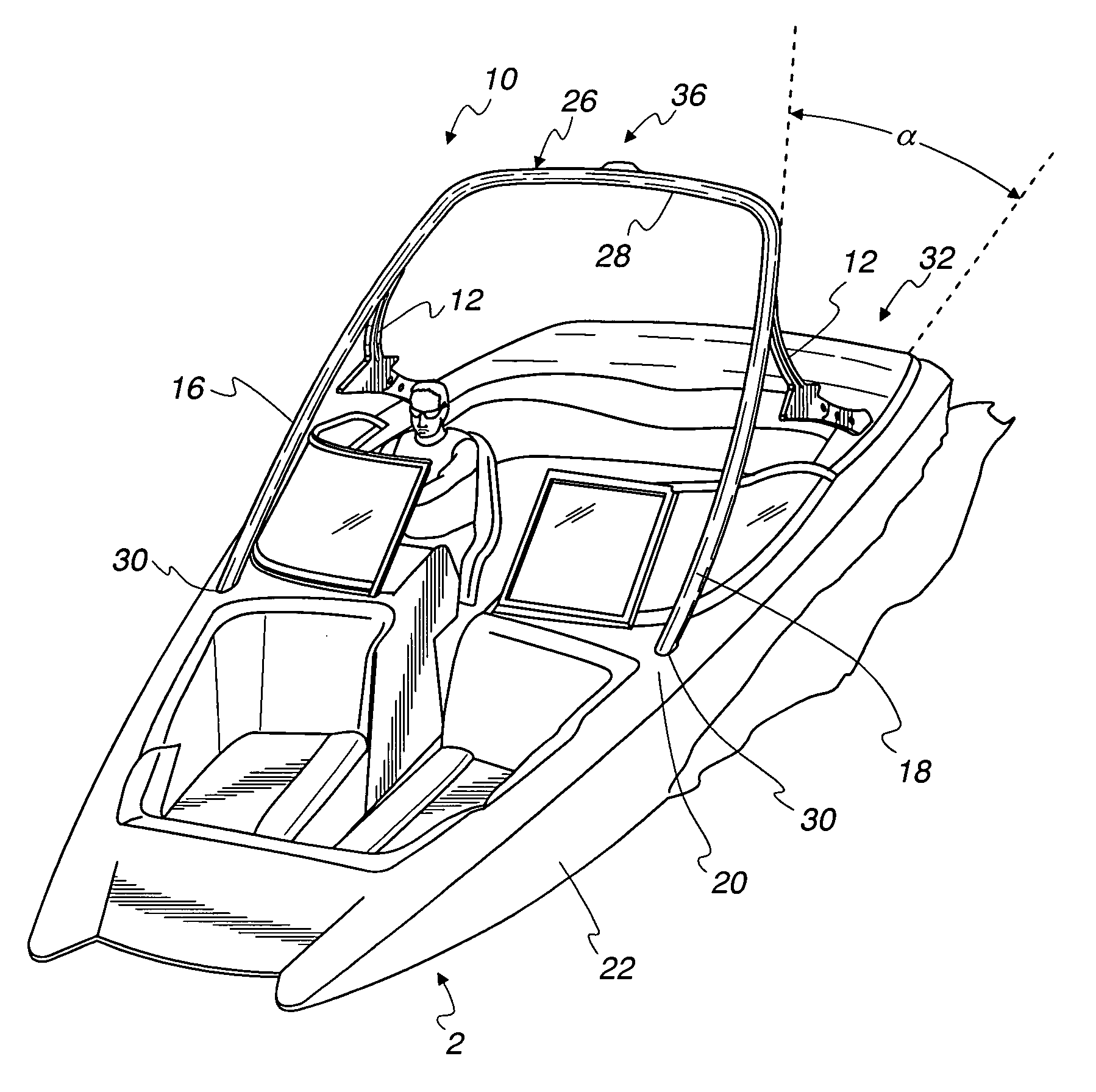
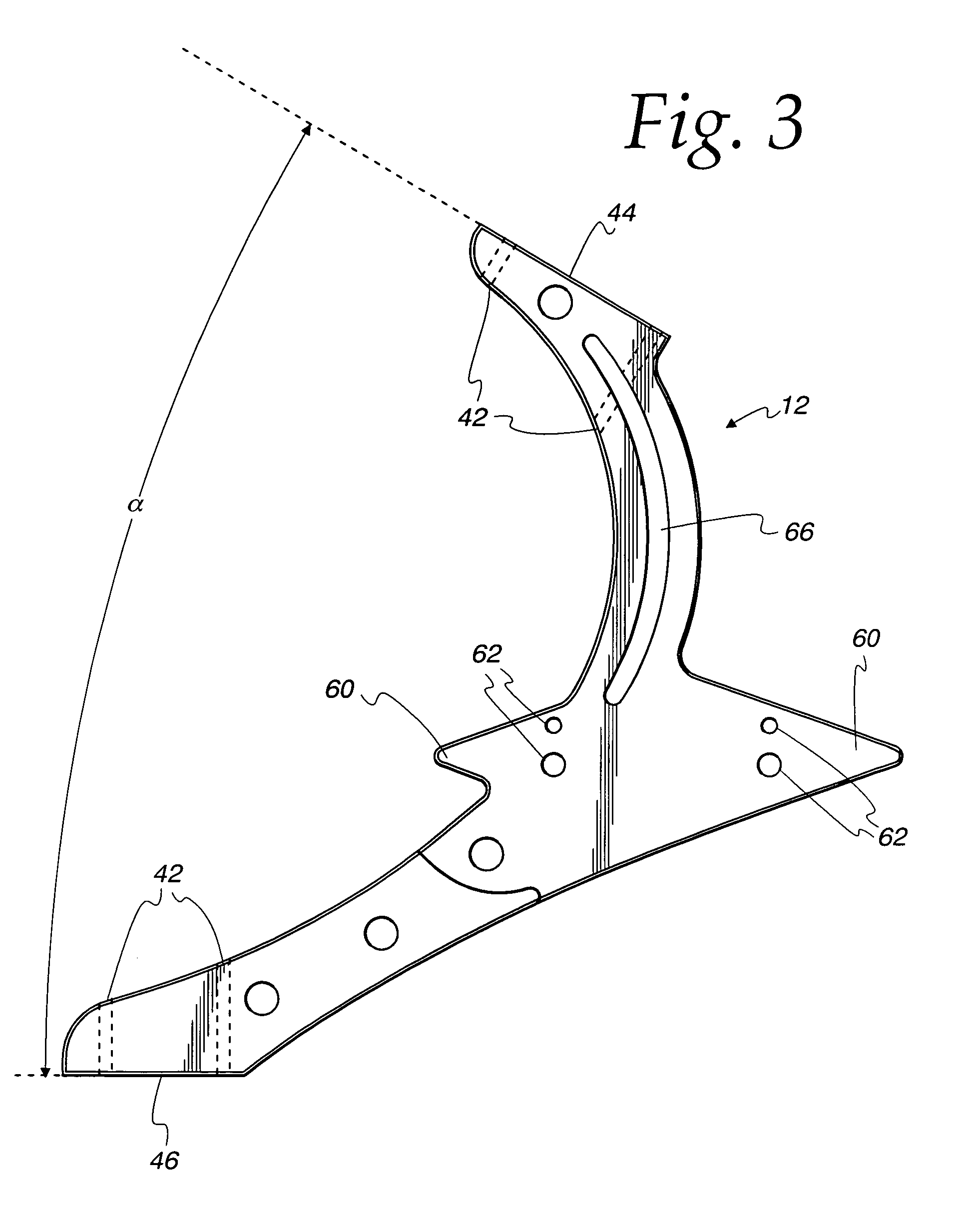
"The present invention provides a new and improved superstructure for towing a person on a surface of a vehicle, such as a boat. The superstructure includes a tower and a support bracket that is removably installed on the boat. The support bracket is attached to the boat at securement points and includes a mounting surface for mounting to the boat and a stanchion face that mounts to the superstructure. The support bracket distributes the compressive force received along the stanchion face through to the mounting surface of the boat. The support bracket can be easily removed and replaced without altering the superstructure. The invention also provides a method for securing the superstructure to the boat and a method for replacing the previously installed support bracket. The technical effects of the invention include improved stability and safety during towing, as well as increased efficiency and flexibility in the installation and replacement of the support bracket."

Problems solved by technology

For the tower permanently mounted to the hull and structure of the boat, it would be difficult and possibly deleterious to the boat if the tower needed replacement, much more so if it were frequent replacement.
In addition, replacement of only a portion of the tower would be similarly difficult if the tower were a single, unitary construction.

Method used


Image

  • Tower and support
  • Tower and support
  • Tower and support

Examples


Embodiment Construction

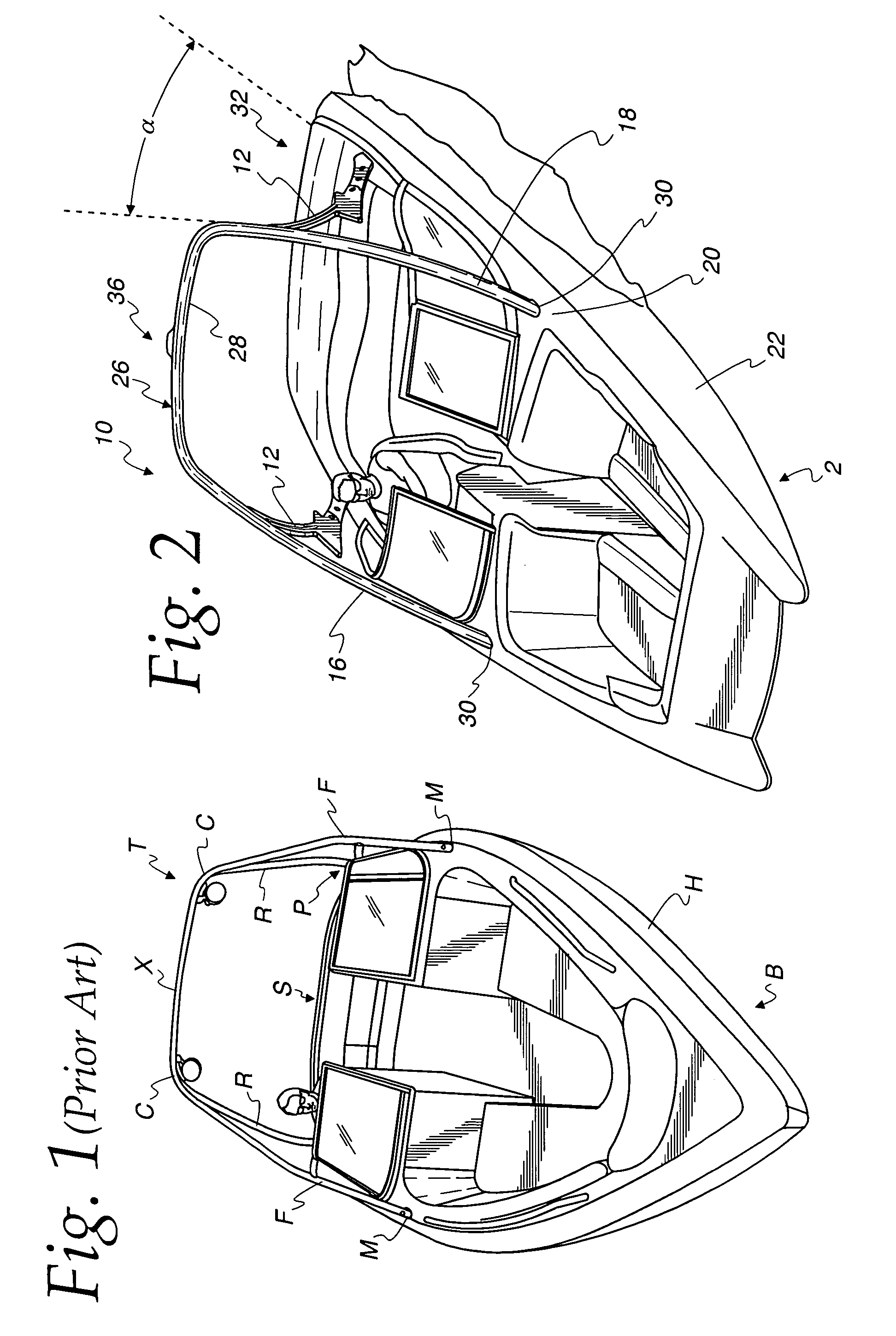
[0021]Referring initially to FIG. 1, a prior art design of a boat B with an accompanying tower T is depicted. As can be generally seen, the tower includes lateral side supports including a pair of front stanchion arms F and a pair rear stanchion arms R. The front stanchion arms F are mounted to a general midship point M of the sides of the boat hull H or decking, rise from the point M, and recede towards the stern S of the boat B. The rear stanchion arms R are mounted to a more aft position P on the sides of the boat hull H, rise from the position P, and recede towards the stern S of the boat B. The top-most points of each stanchion arm F, R meets at a crossbar X. Often and as depicted, the front stanchion arms F and the crossbar X are a single piece of metal tubing bent at corners C to form the requisite shape. The rear stanchion arms R then are joined to the front stanchion arms F and the crossbar X at the corners C, typically by welding the end of the rear stanchion arms to the e...


PUM


Abstract

A support bracket and method for securing and supporting a superstructure for towing persons behind a vehicle such as a boat is disclosed. The support structure has an arcuate face with a length several times that of a tubular member of the superstructure so that the arcuate face provides support over a portion of the tubular member and so that the face mates with the tubular member. The bracket is removably attached and secured to the vehicle and to the superstructure so that it may be removed, or replaced without altering or damaging the superstructure, and so that weld seams are not used. The arcuate face and a second face of the support structure that secures to the boat are set an angle provides a properly erect angle to the superstructure when the bracket, boat, and superstructure are secured.

Description

CROSS-REFERENCE TO RELATED APPLICATIONS[0001]This application is related to U.S. Design Pat. Application No. 29 / 195,185, filed Dec. 8, 2003, entitled “Support.”FIELD OF THE INVENTION[0002]The present invention relates to superstructures for vehicles, and particularly to supports for structures mounted on a vehicle such as a boat used for recreational sports such as water skiing, wakeboarding, kneeboarding, and the like.BACKGROUND OF THE INVENTION[0003]Vehicles may be used for towing or dragging persons or items. Currently, many types of powered boats are used for watersports such as water skiing and wakeboarding. For many years, watersports involving a person being towed behind a boat were principally equipped with a boat whose stern rose from the water's surface less that the height of an average person, though larger boats may have had a higher-positioned stern. Regardless, the mount for the tow rope was located on the stern rail or some other relatively low point. Consequently, t...

Claims


Application Information

Patent Timeline
Patent Type & Authority Patents(United States)
IPC IPC(8): B63B21/56B63B21/58B63B17/00B63B15/00B63B17/02
CPCB63B15/00B63B17/02B63B21/56
Inventor SCHULTZ, JAMES
Owner SCHULTZ JAMES
Learn More