Line connector

Active Publication Date: 2005-06-14
THE COLEMAN CO INC
View PDF5 Cites 6 Cited by
  • Summary
  • Abstract
  • Description
  • Claims
  • Application Information

AI Technical Summary

Benefits of technology

[0014]Disclosed is a line connector, including means for attaching a line, snap-on means for attaching to a snap-in means of a second line connector, snap-in means for attaching to a snap-on means of the second line connector, wherein the snap-in and snap-on portions disposed such that the snap-on portions of first and second line connectors will simultaneously attach onto the snap-in portions of one another along a direction of attachment, and wherein an angle between a direction of attachment is no more than about ninety degrees to an axis of line tension.
[0015]Disclosed is a line connector, including a line attachment portion for connecting a line to a snap-in portion, the

Problems solved by technology

One drawback is the proximity of the inflatables, often making it difficult to access the male and female components to effect the linking and disengagement.
Another drawback to close proximity is that, in the case of pool inflatables, the proximity of the two users may be “too close for comfort.”

Method used


Image

  • Line connector
  • Line connector
  • Line connector

Examples


Embodiment Construction

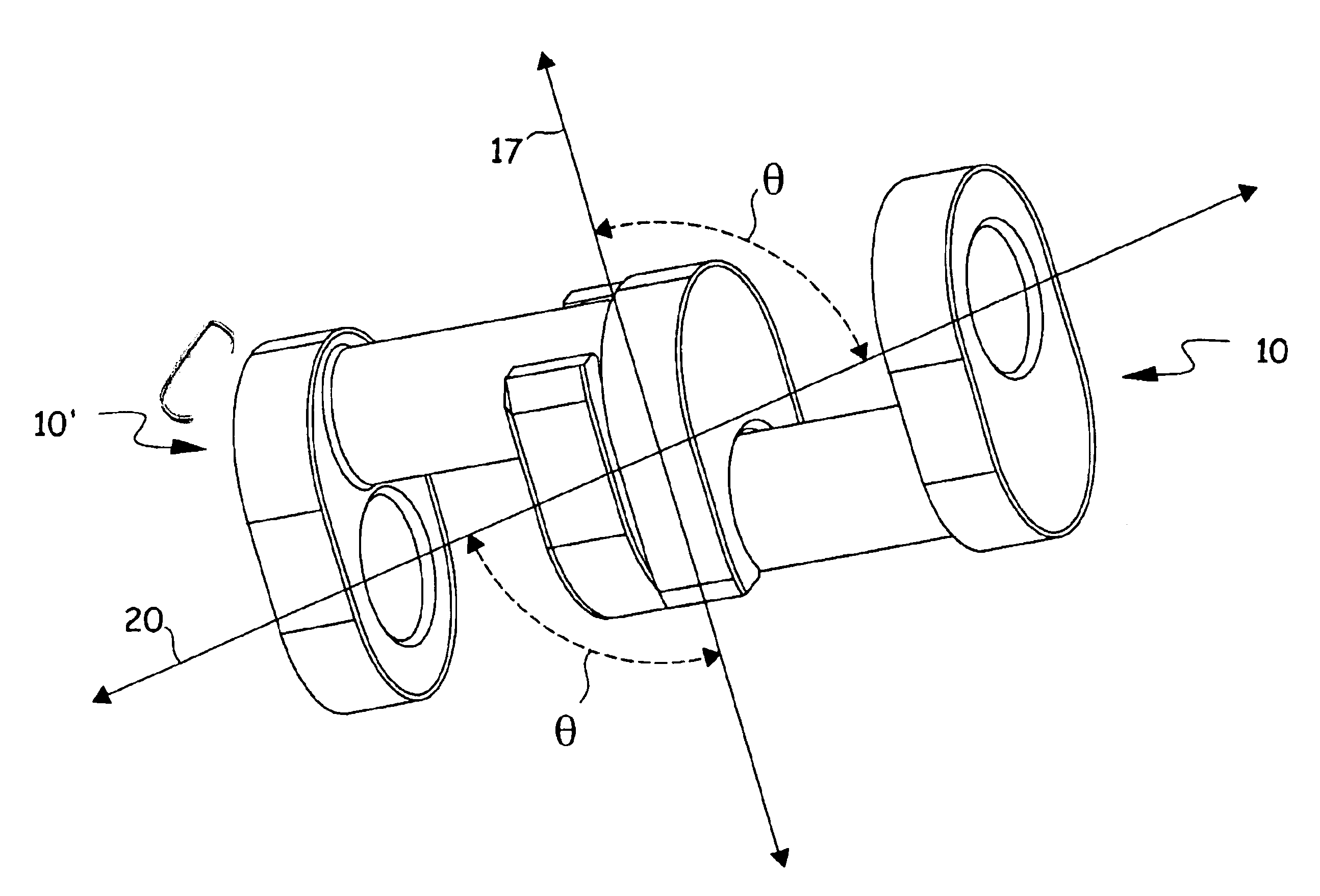
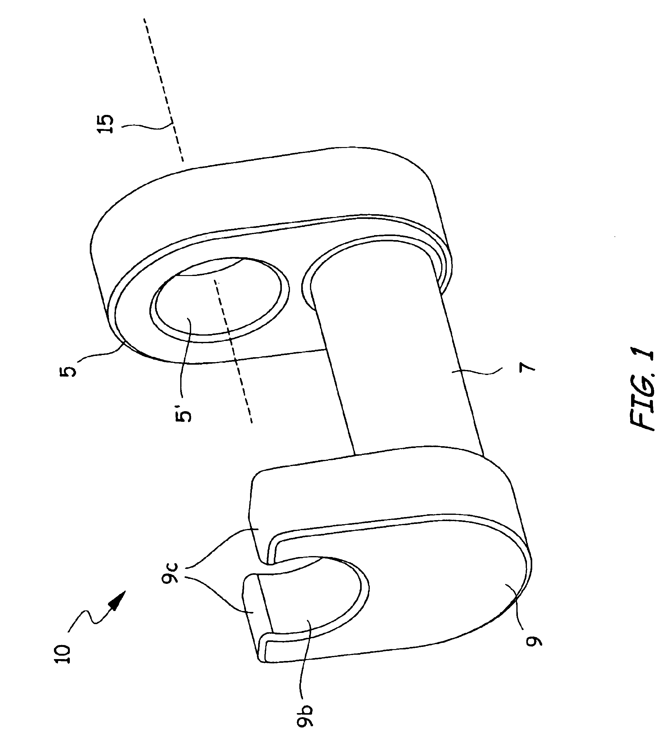
[0020]FIG. 1 shows an embodiment of a line connector 10 of the disclosure having a line attachment portion 5 by which a line 12 (see FIG. 4), such as a cord or wire, may be attached (see also FIG. 4) and thereby define a line axis 15. In this case, the line attachment portion 5 simply comprises an opening 5b adapted to receive the line. Of course, any suitable type of line attachment known in the art may be used. Alternatively, the line 12 may be a part of the connector 10 itself by simply molding a plastic line and connector as a single unit, in which case the line attachment portion 5 is simply the portion where the line ends and the connector begins.

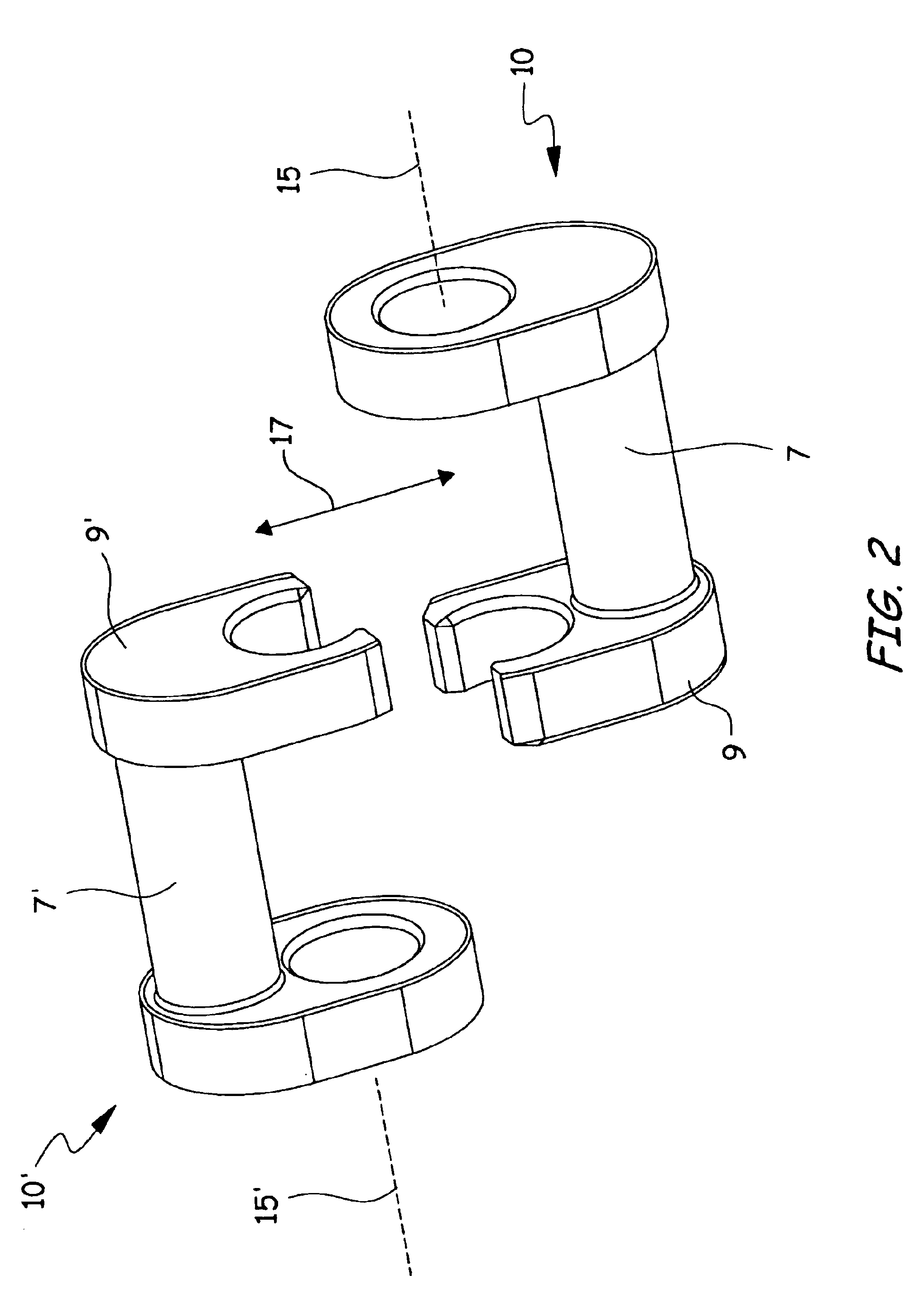
[0021]The line connector 10 also has a snap-in portion 7 and a snap-on portion 9. In the embodiment shown, the snap-in portion 7 is a shaft, optionally cylindrical, and the snap-on portion 9 defines an opening 9b adapted to receive and attach to the snap-in portion 7 of another connector. The terms “snap-on” and “snap-in” are used bec...


PUM

PropertyMeasurementUnit
Lengthaaaaaaaaaa

Abstract

Disclosed is a line connector having a line attachment portion, a snap-in portion, a snap-on portion, wherein the snap-in and snap-on portions disposed such that the snap-on portions of first and second line connectors will simultaneously attach onto the snap-in portions of one another along a direction of attachment, and wherein an angle between a direction of attachment is no more than about ninety degrees to an axis of line tension.

Description

BACKGROUND OF THE DISCLOSURE[0001]1. Field of the Disclosure[0002]This disclosure relates to quick-release connectors for connecting lines such as ropes and cables.[0003]2. Description of the Related Art[0004]Connecting devices for attaching floating devices, such as life rings, pool inflatables, and inflatable rafts, to one another are known in the art. Generally these comprise a female-type receiver and male-type protuberance on the inflatable, such that the male-type protuberance of one inflatable is inserted and locked within the receiver of another, thereby linking the two inflatables. The male is often a t-shape key that is inserted and twisted within the receiver.[0005]One drawback is the proximity of the inflatables, often making it difficult to access the male and female components to effect the linking and disengagement. Another drawback to close proximity is that, in the case of pool inflatables, the proximity of the two users may be “too close for comfort.”[0006]A length...

Claims


Application Information

Patent Timeline
IPC IPC(8): F16G11/10
CPCF16G11/10Y10T403/655Y10T403/4966
Inventor METZGER, ANDREW T.
Owner THE COLEMAN CO INC
Why Eureka
Try Eureka