
Rotary device for retrieving spinal column under treatment

a rotary device and spinal column technology, applied in the field of spinal column surgical care devices, can solve the problems of affecting the outcome of spinal surgery, fixing rods are susceptible to unintentional displacement, etc., and achieve the effects of facilitating threadable engagement, enhancing and enhancing the friction and fastening

Inactive Publication Date: 2005-05-24
A SPINE HLDG FROUP CORP +1
View PDF13 Cites 292 Cited by
  • Summary
  • Abstract
  • Description
  • Claims
  • Application Information

AI Technical Summary

Benefits of technology

[0010]Preferably, said retaining recesses of said fixation seat are located in inner sides of the two side walls of said receiving slot; wherein said retaining edges of said rotary fixation element are located in outer edges of said rotary fixation element. More preferably, said retaining edges of said rotary fixation element are provided with an inclined plane having a higher outer side and a lower inner side; wherein said retaining recesses of said fixation seat are provided with an inclined plane having a higher outer side and a lower inner side, wherein said rotary fixation element is engaged with said fixation seat such that said inclined planes of said rotary fixation element and said fixation seat are in contact with each other, and thus the two side walls of said receiving slot of said fixation seat are further prevented from departing from each other.
[0012]Preferably, a tool hole is provided in said pressing screw for facilitating the threadable engagement with said rotary fixation element.
[0013]Said C-shaped ring of the present invention is elastically retained in the fixation seat and is pressed against the spherical head of the fastening screw, creating more friction between the C-shaped ring and the fixation seat / the spherical head of the fastening screw, so that the fastening thereof is improved. The groove of the C-shaped ring further enhances the friction and the fastening effect.

Problems solved by technology

Although this design improves the conventional backbone-fixing devices, there are at least the following defects which call for further improvements: 1) the contact of the spherical head fastening screw and the fixation rod is restricted to a thin line; and 2) the fixation block has to be fabricated precisely to well fasten the fixation rod in the receiving slot of the fixation seats.
For this reason, the fixation rod is susceptible to unintentional displacement in a spinal surgery in progress.
Such a displacement of the back-retrieving rod often affects adversely the outcome of the spinal surgery.

Method used


Image

  • Rotary device for retrieving spinal column under treatment
  • Rotary device for retrieving spinal column under treatment
  • Rotary device for retrieving spinal column under treatment

Examples


Embodiment Construction

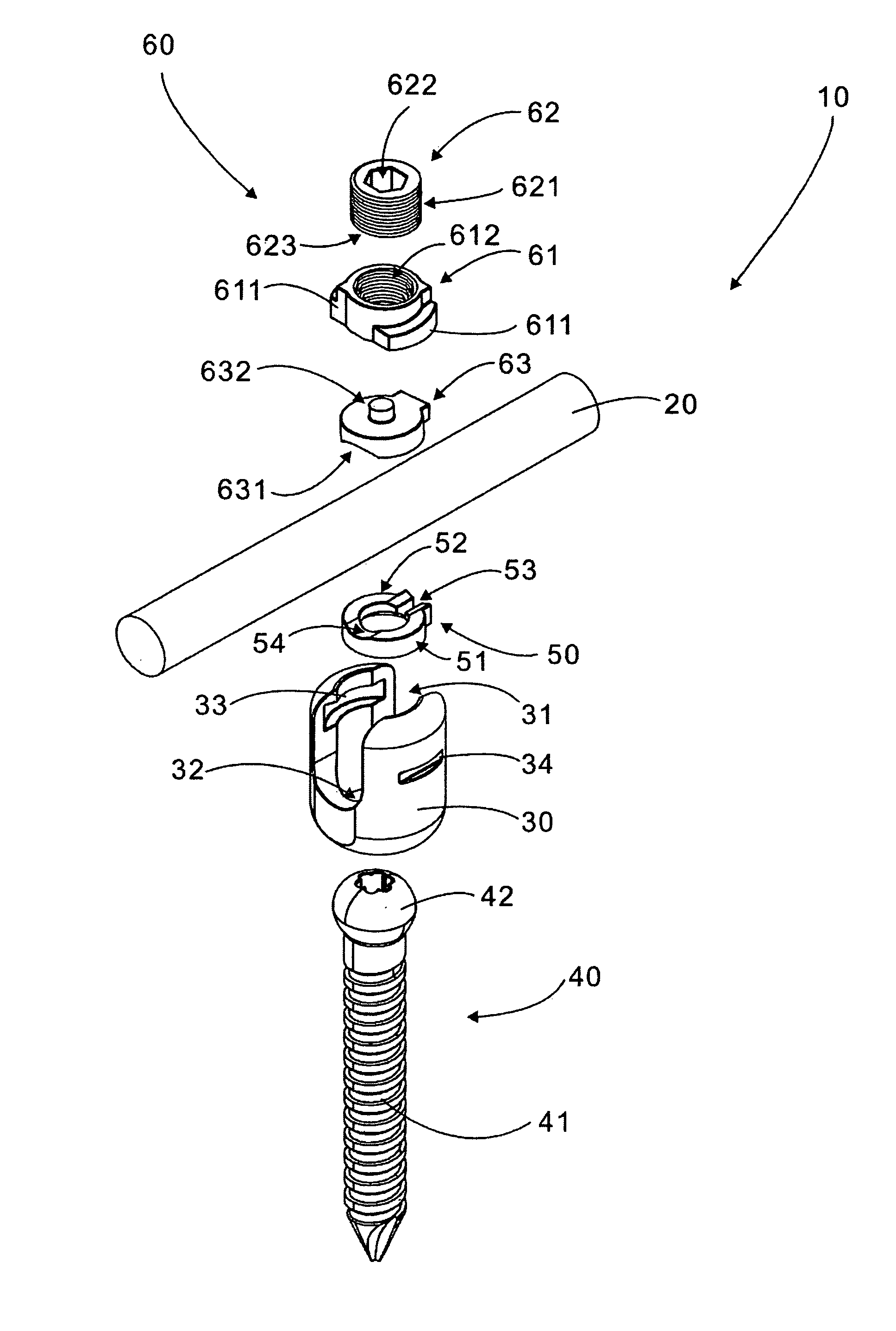
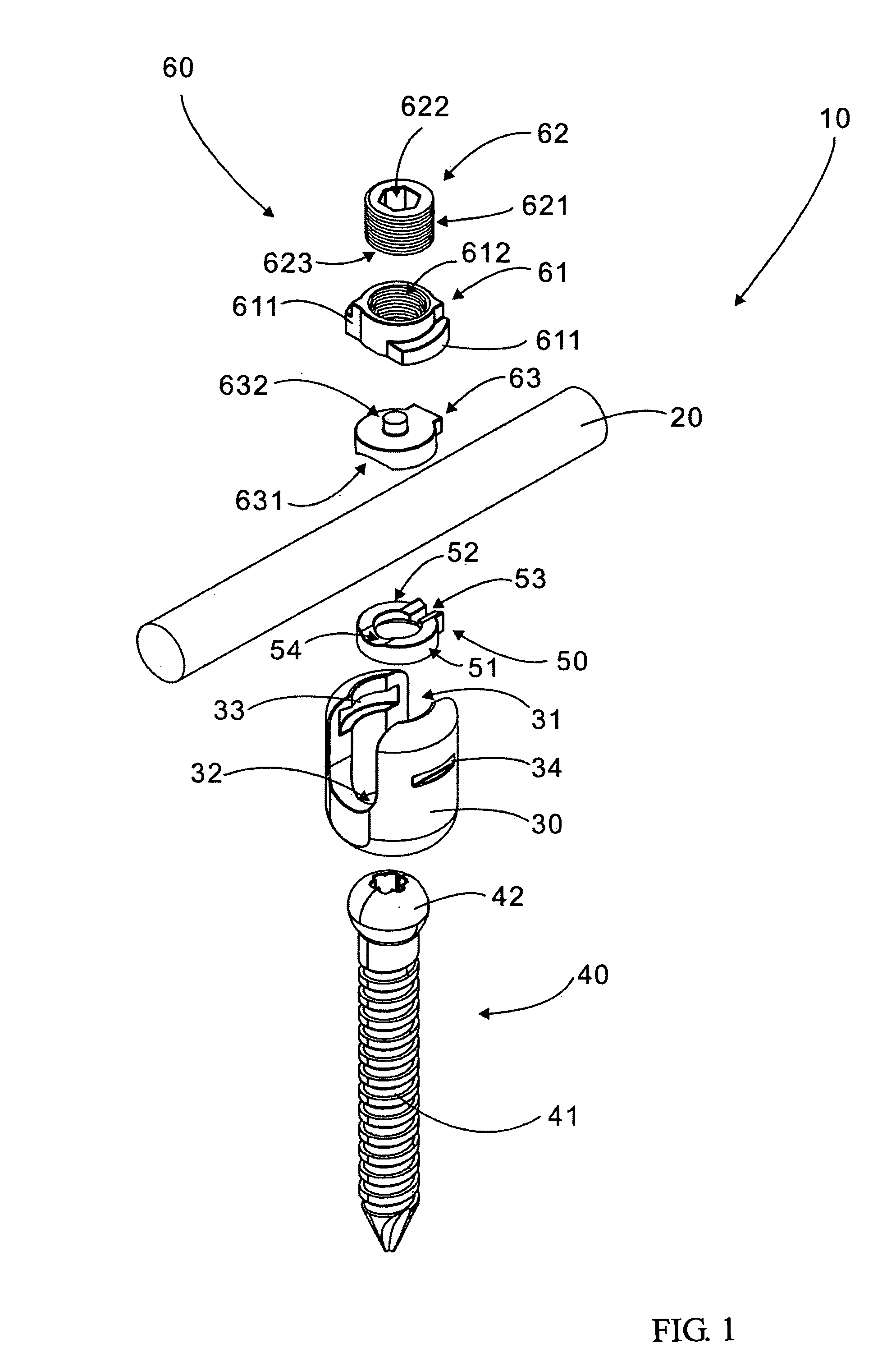
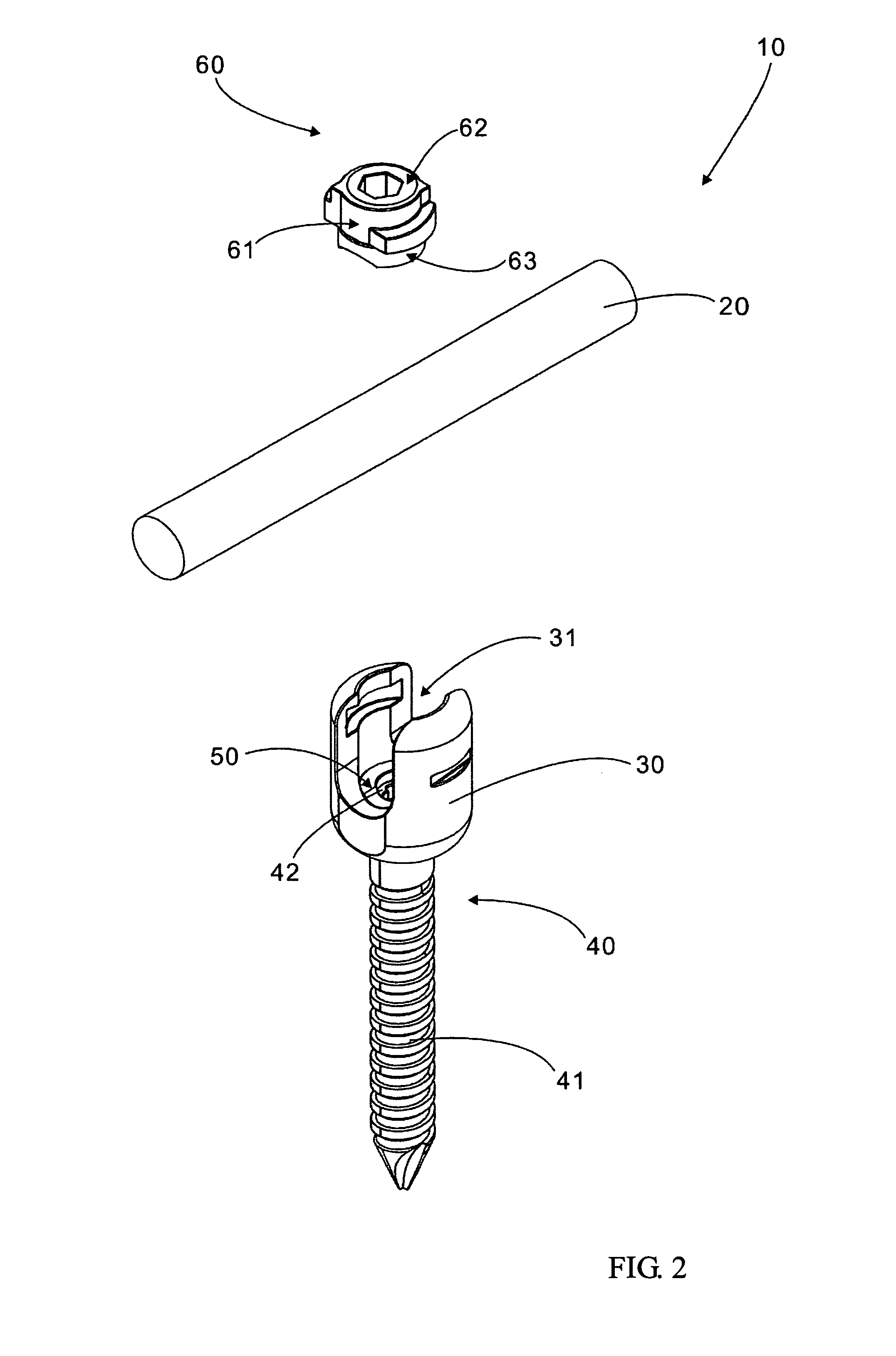
[0020]As shown in FIGS. 1–4, a vertebral retrieval device 10 of the present invention comprises a retrieval rod 20, a fixation seat 30, a fastening screw 40, a C-shaped ring 50, and a fixation assembly 60.

[0021]The fixation seat 30 is provided with a U-shaped receiving slot 31 which has two retaining recesses 33 on the two inner walls, two clamping slots 34 on the outer walls, and a through hole 32 in the bottom.

[0022]The fixation assembly 60 has a rotary fixation element 61, a pressing screw 62 and a pressing element 63, which can be assemble before using, as shown in FIG. 2. The rotary fixation element 61 is provided with a threaded through hole 612 at the axial center, and two opposite retaining edges 611 protruding radially from the outer surface. The pressing element 63 has a cylindrical projection 632 at one side and a groove 631 at another side. The pressing screw 62 has a round hole 623 for receiving said projection 632 of said pressing element, and is threadably engaged in ...


PUM


Abstract

A vertebral retrieval device includes a retrieval rod which is gripped firmly in a receiving slot of a fixation seat between two grooves of a pressing element and a C-shaped ring. The C-shaped ring rests on a spherical head fastening screw, a spherical head of which is received in the fixation seat and a shank of which is protruding from a through hole provided in a bottom of the fixation seat. The pressing element is pressed against the retrieval rod by a pressing screw, which is threaded into a threaded hole formed in a fixation element mounted in the receiving slot of the fixation seat.

Description

FIELD OF THE INVENTION[0001]The present invention relates generally to a spinal surgical care device, and more particularly to a rotary device for retrieving spine column under treatment.BACKGROUND OF THE INVENTION[0002]The inventor of this application in U.S. patent published No. 20030187434 A1 discloses a vertebral fixation device comprising a fixation seat, a fixation block, and a fastening bolt. The fixation seat is provided with a receiving slot for receiving a vertebral fixation rod. The fixation block is engaged with the fixation seat such that the vertebral fixation rod is pressed by the fixation block, and that two retaining edges of the fixation block are retained in two retaining recesses of the fixation seat. The fastening bolt is engaged with a threaded through hole of said fixation block such that one end of the fastening bolt presses against the vertebral fixation rod. Although this design improves the conventional backbone-fixing devices, there are at least the follo...

Claims


Application Information

Patent Timeline
IPC IPC(8): A61B17/70A61B17/58
CPCA61B17/7037A61B17/7032
Inventor LIN, CHIH-I
Owner A SPINE HLDG FROUP CORP
Learn More