
Portable flat-faced interactive training soccer goal

a soccer goal and interactive technology, applied in the field of soccer goals, can solve the problems of modest increase in net cost, and achieve the effect of increasing net tension

Inactive Publication Date: 2005-05-17
GRUNFELD DAN
View PDF21 Cites 30 Cited by
  • Summary
  • Abstract
  • Description
  • Claims
  • Application Information

AI Technical Summary

Benefits of technology

[0009]Another key object of the invention is to provide soccer players with a greatly improved soccer goal that helps hone follow-up shots.
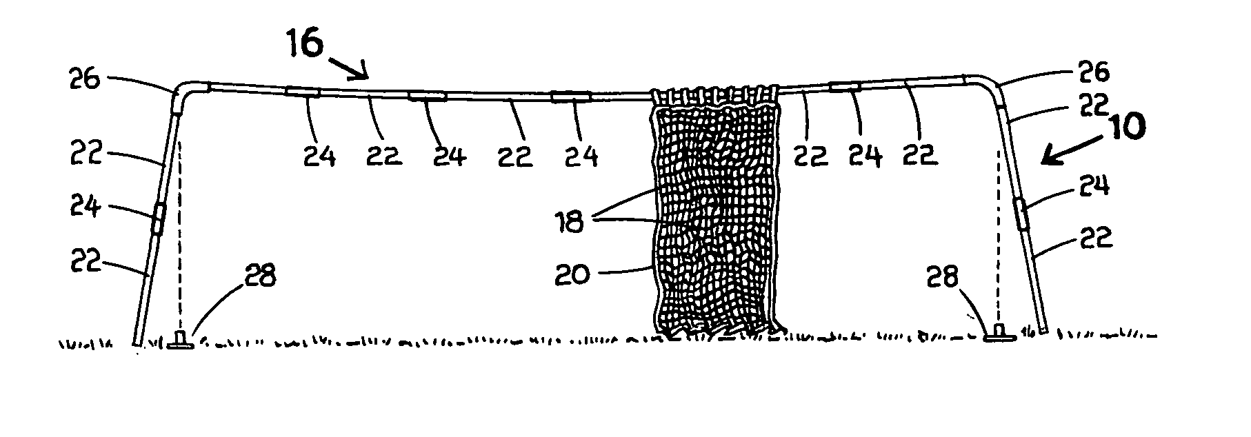
[0010]Still another object of the invention is the flat-faced soccer goal helps maximize the efficiency of practice drills by simulating a traditional soccer goal but will quickly rebound the ball. In this manner, a player can take a series of rapid-fire shots on the goal and / or take a power shot on the goal and immediately follow through with a rebounding shot after the first shot is deflected back out of the goal.
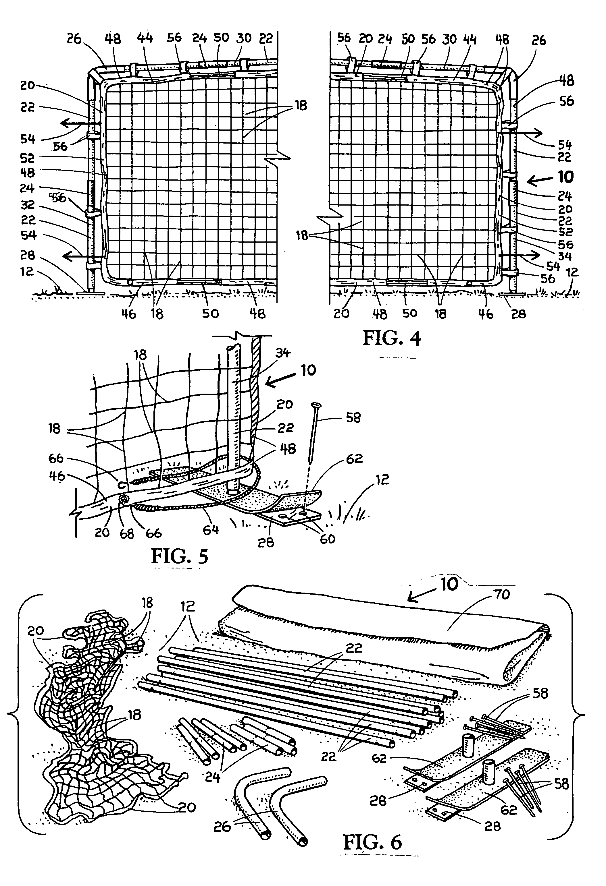
[0011]A further object of the invention is the net is attached to a web frame. The web frame is interspersed with both non-stretch webbing and stretch webbing. The combination of the stretch and non-stretch web frame provides increased tension on the net, when attached to the soccer goal frame, for improved rebounding and with a modest increase in net cost.
[0012]Still a further object and important feature of the invention is the soccer goal frame is erected using tube sections and connector sleeves that are compressed together when two upright posts that are attached to opposite ends of a horizontal crossbar are moved inwardly from a trapezoidal configuration with the ground surface to a rectangular configuration with the ground surface and inserted into ground engaging post bases. The bending and compression of the upright posts prevents the tube sections and sleeves, making up the horizontal crossbar and the posts, from coming loose or being jarred loose during the use of the goal. Also, the compression of the goal frame greatly increases the strength and rigidity of the frame when the net and web frame are secured thereon.
[0013]Yet another object of the flat-faced portable soccer goal is the goal is portable, lightweight, roughed in construction and can be quickly and easily setup for soccer practice and training. Obviously by design, the flat-faced soccer goal can be used for soccer practice on both sides of the net.
[0014]The flat-faced soccer goal includes a goal frame made up of a plurality of metal tube sections joined together by plurality of connector sleeves and a pair of corner elbow sleeves for forming a pair of upright posts and a horizontal crossbar. A top portion of the upright posts is joined to opposite ends of the crossbar using the corner elbow sleeves. The corner elbow sleeves are bent at an angle greater than 90 degrees and upward to 110 degrees thus forming a trapezoid configuration with the crossbar being parallel to the ground surface. The upright posts are disposed outwardly and at an angle from the vertical. When the goal frame is installed, the upright posts are moved inwardly into a perpendicular position with respect to the ground and parallel to each other for forming a rectangular configuration with the ground surface. The movement of the upright posts into a perpendicular position provides a bending movement or torque on the tube sections and connector sleeves thereby compressing them together in a lock fit and preventing the goal frame from coming loose or being disassembled during use. A soccer goal net having a web frame is attached to the horizontal crossbar and the upright posts. The web frame can include non-stretch webbing or a combination of non-stretch webbing and stretch webbing for increased tension on the net.

Problems solved by technology

The combination of the stretch and non-stretch web frame provides increased tension on the net, when attached to the soccer goal frame, for improved rebounding and with a modest increase in net cost.

Method used


Image

  • Portable flat-faced interactive training soccer goal
  • Portable flat-faced interactive training soccer goal
  • Portable flat-faced interactive training soccer goal

Examples


Embodiment Construction

[0026]In FIG. 1, a perspective view of the subject portable flat-faced interactive soccer goal is shown and having general reference numeral 10. The goal 10 is illustrated fully assembled and installed vertically on a portion of a ground surface 12 making up a playing field. A pair of soccer players 14 are shown in action on both sides of the flat-faced soccer goal 10.

[0027]Broadly, the soccer goal 10 includes a goal frame, having general reference numeral 16, for holding in tension a soccer goal net 18 with a web frame 20 attached to a perimeter of the net. The web frame 20 is shown in greater detail in FIGS. 4–6. The goal frame 16 includes a plurality of metal tube sections 22, a plurality of connecting sleeves 24, a pair of corner elbow sleeves 26 and a pair of ground engaging post bases 28.

[0028]When assembling the goal frame 16, tube sections 22, having a length of approximately 43 inches, are connected together using five connecting sleeves 24, having a length of approximately...


PUM


Abstract

A flat-faced interactive training soccer goal used for soccer practice. The soccer goal has a goal frame held in compression and a net and web frame held in tension for increased rebounding of a soccer ball. The flat-faced soccer goal includes a goal frame made up of a plurality of metal tube sections joined together by plurality of connector sleeves and a pair of corner elbow sleeves for forming a pair of upright posts and a horizontal crossbar. A top portion of the upright posts is joined to opposite ends of the crossbar using the corner elbow sleeves. The corner elbow sleeves are bent at an angle greater than 90 degrees and upward to 110 degrees for forming a trapezoid configuration with the crossbar being parallel to the ground surface. The upright posts are disposed outwardly and at an angle from the vertical. When the goal frame is installed, the upright posts are moved inwardly into a vertical position for forming a rectangular configuration.

Description

[0001]This application is a continuation-in-part application of an application filed on Apr. 27, 2001, Ser. No. 09 / 844,502 now abandoned, having a title of “METHOD AND APPARATUS FOR PORTABLE FLAT FACED REBOUNDING SOCCER TRAINING GOAL” and by the subject inventor, Dan Grunfeld.BACKGROUND OF THE INVENTION[0002](a) Field of the Invention[0003]This invention relates to soccer goals and more particularly, but not by way of limitation, to a portable flat-faced interactive training soccer goal having a goal frame held in compression and a net held in tension. The net can include a combination of stretch and non-stretch webbing making up a webbing frame. The flat-faced soccer goal is used for practice and training.[0004](b) Discussion of Prior Art[0005]Heretofore, there have been a variety of different types of portable training goals and practice goals. In U.S. Pat. No. 4,083,561 to Daffer a soccer practice goal is disclosed. In U.S. Pat. No. 4,116,446 to Thompson a game net support appara...

Claims


Application Information

Patent Timeline
IPC IPC(8): A63B69/00A63B63/00
CPCA63B69/0097A63B63/004
Inventor GRUNFELD, DAN
Owner GRUNFELD DAN
Learn More