Hinge

a technology of hinges and hinges, applied in the field of hinges, can solve the problems of unchangeable screw connections between the hinges and the walls of the piece of furniture, and achieve the effects of reducing the size of the hinge, and ensuring the mutual alignment of the individual elements

Inactive Publication Date: 2005-04-26
ARTURO SALICE
View PDF18 Cites 8 Cited by
  • Summary
  • Abstract
  • Description
  • Claims
  • Application Information

AI Technical Summary

Benefits of technology

[0003]It is the object of the present invention to provide a hinge which allows a simple adjustment to the height of the door leaf with respect to the body of the piece of furniture with a small installation size. This object is solved by a hinge having the features herein. Advantageous aspects also form the subject herein.

Problems solved by technology

With the hinge of the prior art, an unchangeable screw connection is provided between the hinge and the wall of the piece of furniture.

Method used


Image

  • Hinge
  • Hinge
  • Hinge

Examples


Embodiment Construction

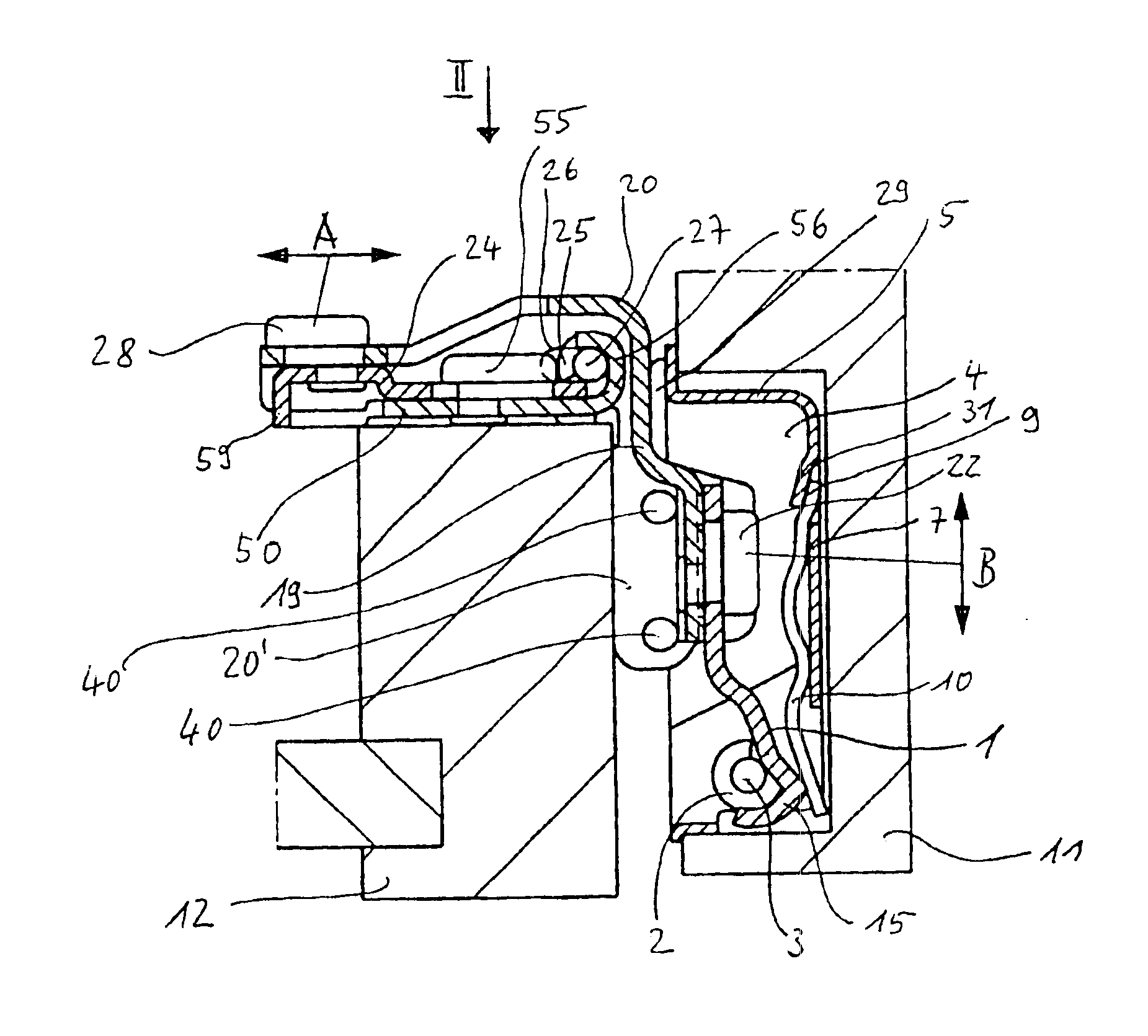
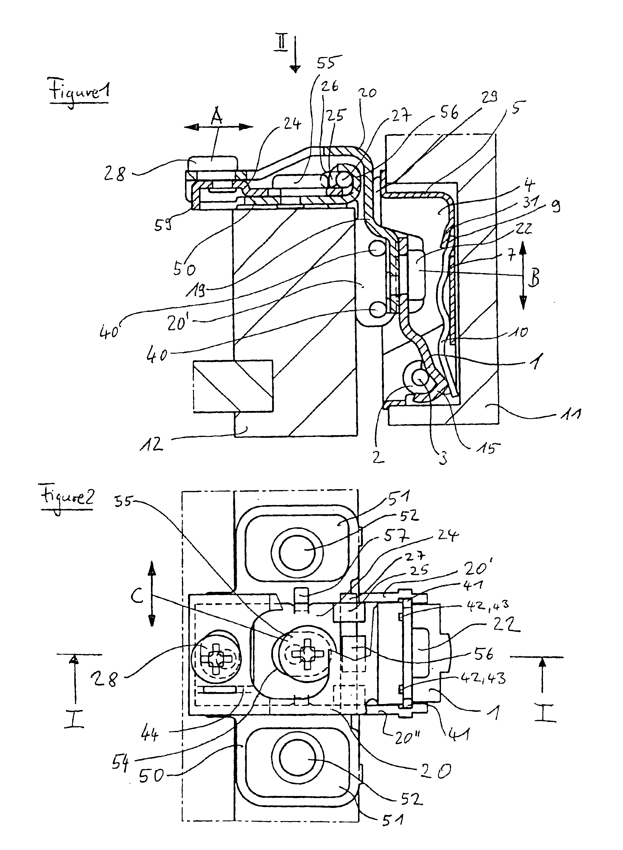
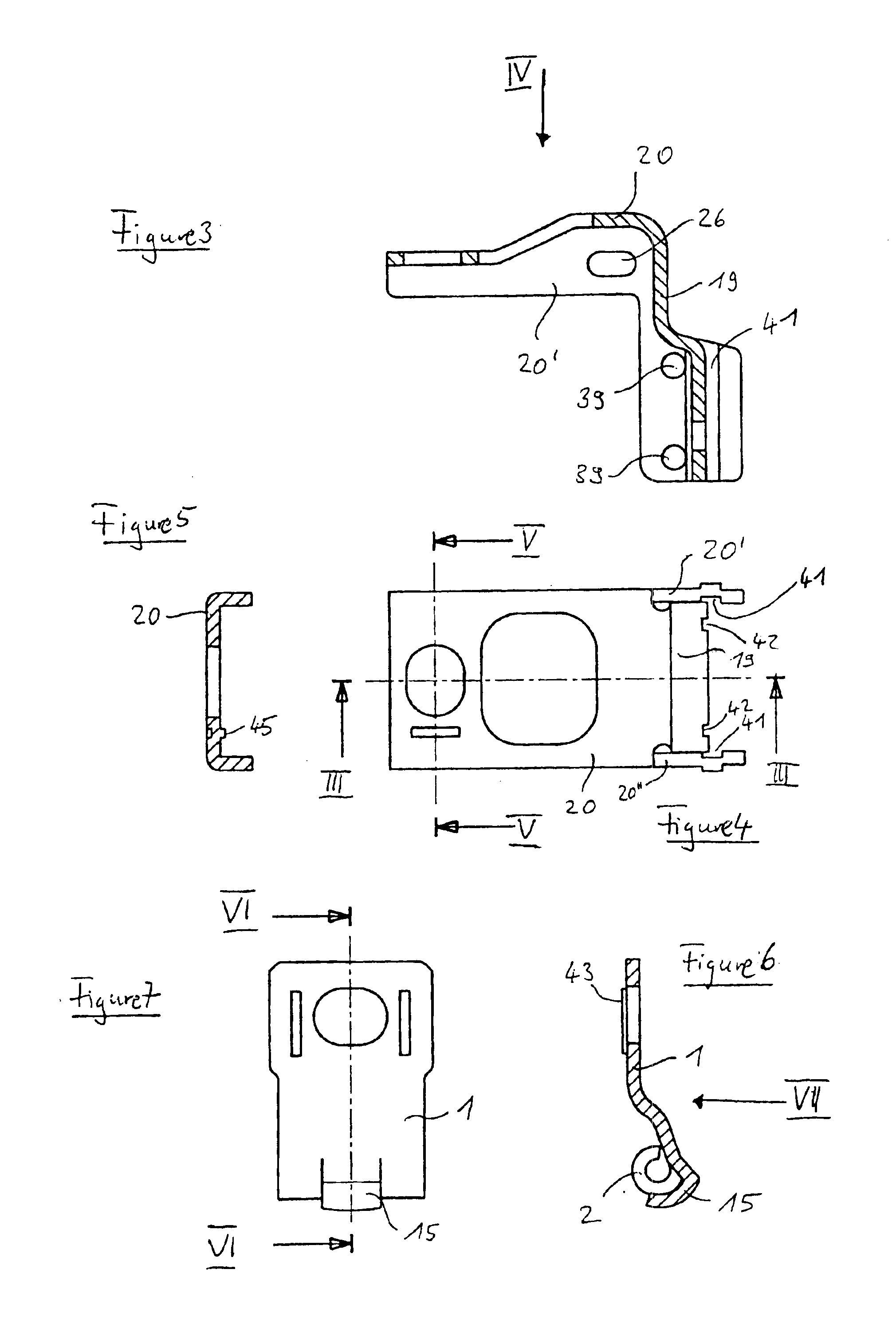
[0029]The hinge visible from FIGS. 1 and 2 consists of a hinge arm 1 provided with a bend, said hinge arm 1 enclosing with its lower rolled-in end 2 a joint axle 3 which, so to say, forms a bearing bore for this. The joint axle 3 is undisplaceably supported in a usual manner in the side walls of the pot-shaped hinge part 4. A tongue 31 is bent out of the base 7 of the pot-shaped hinge part 4 by a corresponding free cut. A slit is thereby formed in the base 7 into which the rear end 9 of a plate spring 10 is inserted. A cam 15 is bent out of the rolled-in part 2 of the hinge arm 1 and forms the lever arm for the plate spring 10. The pot-shaped hinge part 4 is inserted in a usual manner into a shallow blind aperture bore, for example of a door 11 of a piece of furniture and connected to this by a flange 29 which is part of the pot-shaped hinge part 4.

[0030]The hinge arm 1 is connected to the end face 19 of the holding arm 20 via an eccentric element 22 in a manner known per se to the ...


PUM


Abstract

The invention relates to a hinge, preferably a furniture hinge, comprising a hinge arm which is pivotally connected, at one end, via a joint axle to a hinge part and, at the other end, via holding means to a base element, preferably to a base plate. Provision is made in accordance with the invention for the holding means to comprise a first eccentric adjustment, preferably retained by friction, for displaceable holding which allows a displacement parallel to the joint axle.

Description

BACKGROUND OF THE INVENTION[0001]The invention relates to a hinge, preferably to a furniture hinge, comprising a hinge arm which is pivotally connected, at one end, via a joint axle to a hinge part and, at the other end, via holding means to a base element, preferably to a base plate.[0002]Such a hinge of this kind is described in U.S. Pat. No. 6,360,401 B1. Such hinges are e.g. used for fastening door leaves to walls of pieces of furniture. With the hinge of the prior art, an unchangeable screw connection is provided between the hinge and the wall of the piece of furniture. A fastening would be desirable which allows a vertical adjustment of the hinge and thus of the door leaf with respect to the wall of the piece of furniture. For this purpose a fastening is provided in DE 299 20 945 U1 which allows a vertical displacement of the hinge along an elongate opening provided in a base plate of the hinge on the loosening of a fastening screw which serves the fastening of the hinge in th...

Claims


Application Information

Patent Timeline
Patent Type & Authority Patents(United States)
IPC IPC(8): E05D5/08E05D11/00E05D11/10E05D7/04E05D5/00E05F1/00E05F1/12E05D5/06
CPCE05D5/065E05D5/08E05D7/0415E05D11/1014E05D2007/0469Y10T16/5321E05F1/1284E05Y2900/20Y10T16/554Y10T16/53253Y10T16/5324E05D2007/0484E05D3/06
Inventor SALICE, LUCIANO
Owner ARTURO SALICE
Why Eureka
Try Eureka