
Modular furniture

a technology of modular furniture and furniture, applied in the field of modular furniture, can solve the problems of not having the structural strength required for a number of furniture items, unable to adapt to immediate needs, and affecting the quality of finished products,

Inactive Publication Date: 2005-04-12
WINKLESS CHRISTINE ELIZABETH
View PDF49 Cites 51 Cited by
  • Summary
  • Abstract
  • Description
  • Claims
  • Application Information

AI Technical Summary

Benefits of technology

Further, a base projection frame can be used in conjunction with one or more modules, the frame being operable to fit around the base projections of the one or more modules. Where the base projection frame is operable to fit around the base projections of two or more of the modules, the frame can restrict horizontal movement of the modules.

Problems solved by technology

While these traditional modular furniture systems allow for a customized configuration that is suited for a specific environment, taste, budget, they do not generally allow for rapid dynamic reconfiguration of the furniture to suit immediate needs.
While Overby's system provides for modular furniture that is relatively easily disassembled, the constructs do not possess the structural strength required for a number of furniture items.
Further, the finished product is marred by a number of projections and indentations.
While the system disclosed by O'Neill allows the modular furniture to be rapidly reconfigured to suit varying immediate needs, it suffers from a relatively high cost of manufacture in that the circular projections generally must be machined and affixed to the top of the module and bores must be made in the bottom of each module.
The cubes themselves, however, do not have any interlockingly engaging features to stabilize a completed product.
Further, no method for securing laterally placed modules is available, thus allowing the structure to shear horizontally.

Method used


Image

  • Modular furniture
  • Modular furniture
  • Modular furniture

Examples


Embodiment Construction

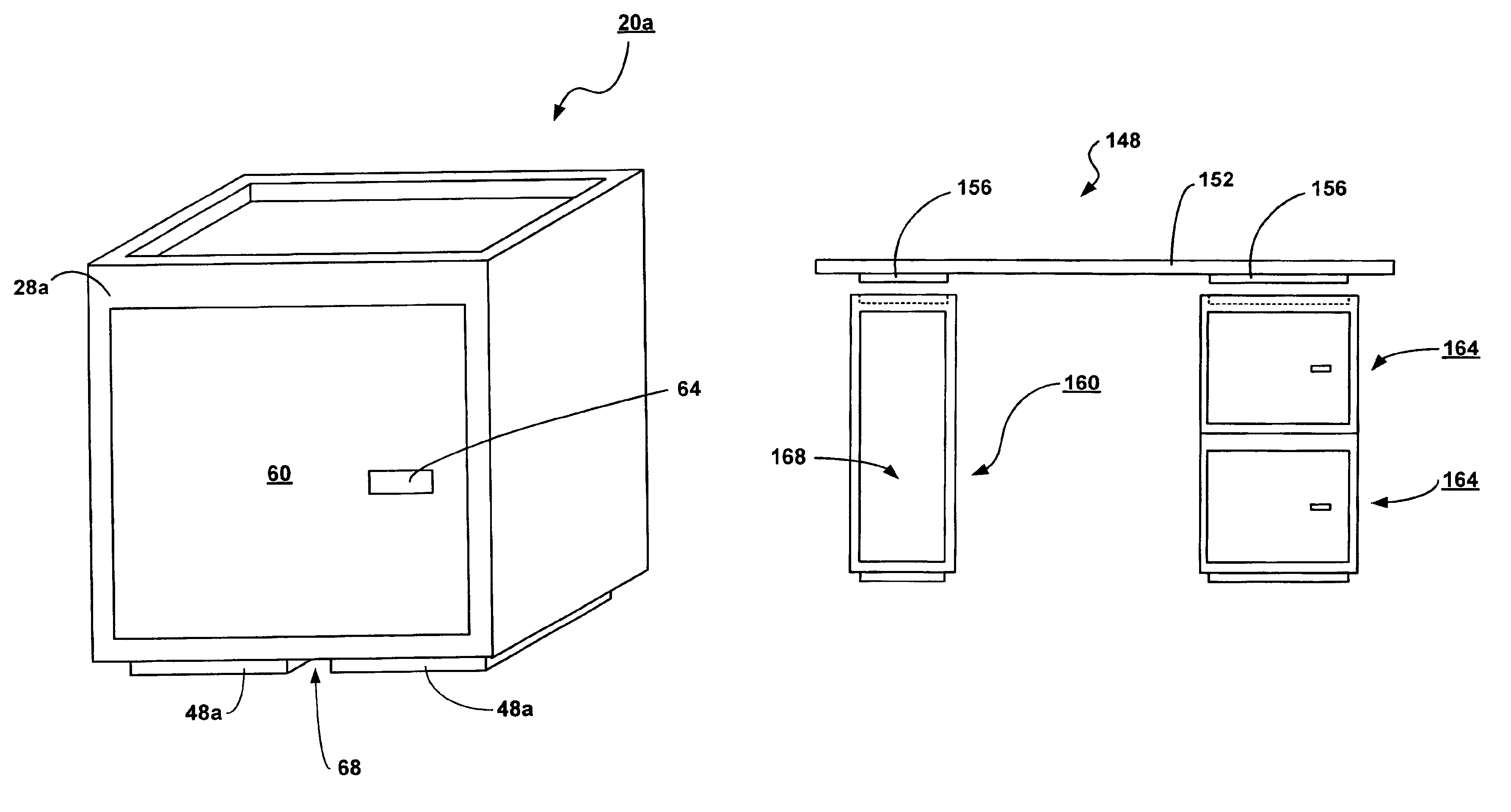
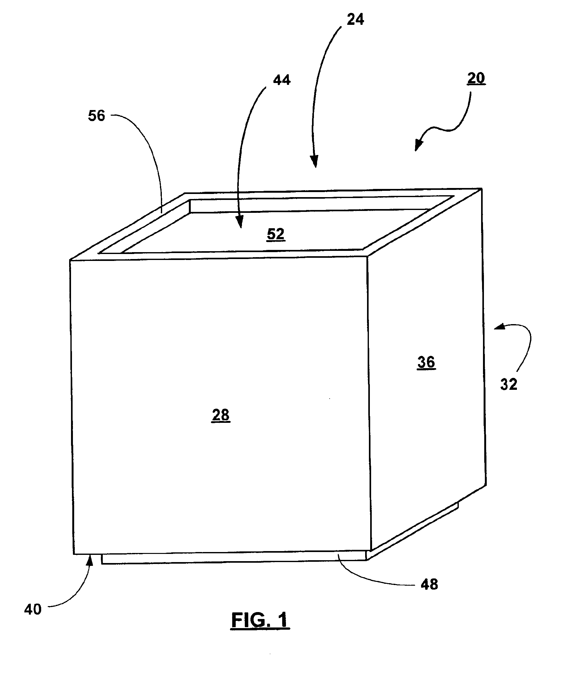
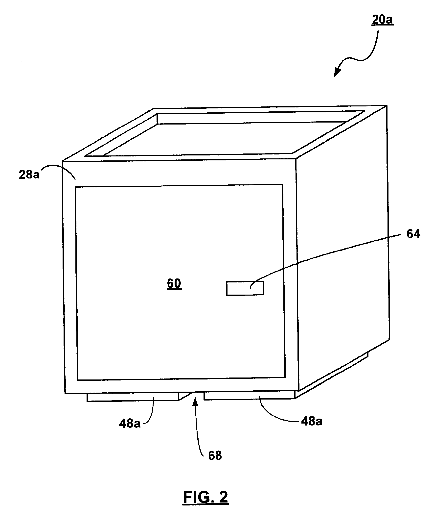
A module for providing modular furniture in accordance with an embodiment of the invention is generally shown at 20 in FIG. 1. Module 20 has a top wall 24, a front wall 28, a back wall 32, two side walls 36, and a bottom wall 40. In the embodiment shown in FIG. 1, module 20 is generally cubic, but other variations will occur to those skilled in the art that are suitable for side-by-side placement and stacking, such as a box-like structure having a length, a width and a depth of different lengths. Top wall 24 has a recess 44. Bottom wall 40 has a base projection 48 corresponding to recess 44, allowing modules 20 to be stacked one atop another.

In the embodiment shown in FIG. 1, recess 44 has a one-inch depth and has a cross-area defined by a perimeter offset one inch from the outer perimeter of module 20, thus defining a sub-top wall 52 and a lip 56. Correspondingly, base projection 48 is like-dimensioned, having a depth of one inch and a cross-area defined by a perimeter offset one i...


PUM


Abstract

A system for modular furniture is provided, consisting of a plurality of modules, each having a front wall, a back wall, a left wall, a right wall, a top wall and a bottom wall, the top wall having a recess and the bottom wall having at least one projection corresponding to and operable to fit within and securely engage the recess when a first of the modules is vertically stacked atop of a second of the modules. The modules can be interengagingly and securely stacked either directly atop other modules or staggered atop two or more others to provide a desired configuration. A number of adapters can be used with the modules to provide a number of customized solutions.

Description

FIELD OF THE INVENTIONThe present invention relates generally to modular furniture. More specifically, the present invention relates to a system of reconfigurable basic units forming furniture.BACKGROUND OF THE INVENTIONModular furniture generally refers to furniture that is assembled from a number of basic modules that, in combination, provide the functionality required. The basic modules can be configured by a user to provide a number of configurations. Each configuration can vary in terms of size, utility, design, color, etc. The finished product is typically permanently fastened together in the desired configuration and deployed. While these traditional modular furniture systems allow for a customized configuration that is suited for a specific environment, taste, budget, they do not generally allow for rapid dynamic reconfiguration of the furniture to suit immediate needs.More recently, a number of modular furniture solutions have appeared on the market wherein the modules can ...

Claims


Application Information

Patent Timeline
IPC IPC(8): A47B87/00A47B87/02
CPCA47B87/008A47B87/0292A47B87/02
Inventor WINKLESS, CHRISTINE ELIZABETH
Owner WINKLESS CHRISTINE ELIZABETH
Learn More