
Tools for interacting with virtual environments

a virtual environment and tool technology, applied in the field of tools for interacting with virtual environments, can solve the problems of inability to learn, incompatible with standard ways, and still have a number of difficulties and limitations

Inactive Publication Date: 2005-01-11
FRAUNHOFER GESELLSCHAFT ZUR FOERDERUNG DER ANGEWANDTEN FORSCHUNG EV
View PDF4 Cites 448 Cited by
  • Summary
  • Abstract
  • Description
  • Claims
  • Application Information

AI Technical Summary

Benefits of technology

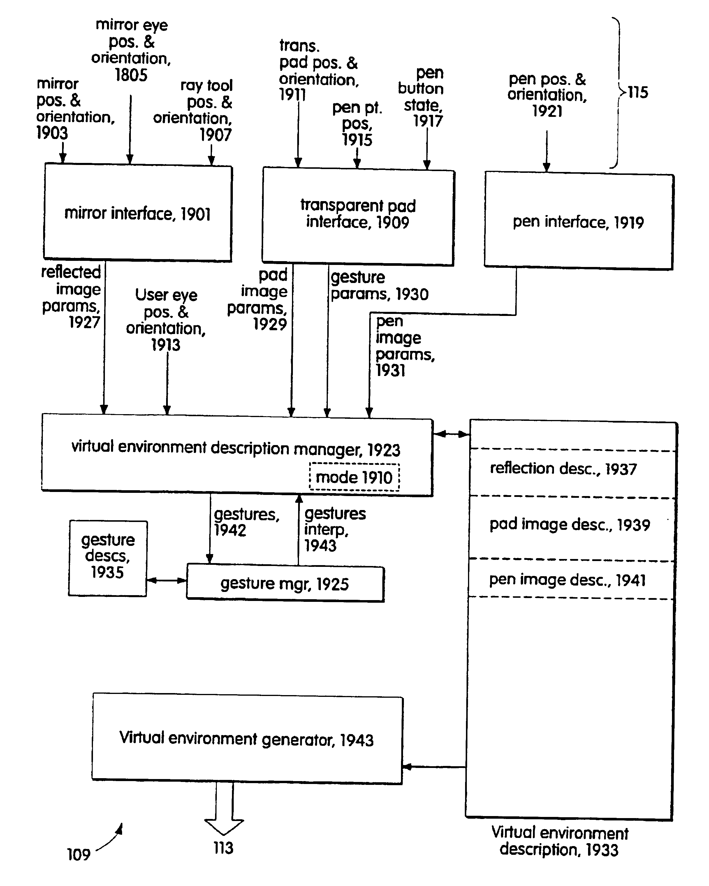
The device that is used to view the portion may be fixed or movable relative to the virtual environment, as may be the given direction and point of view. Where both are movable, the given direction and point of view may be those of the eyes of a user of the virtual environment system and the device may be held in the user's hand. Modes of operation of the device may depend on the position of the device relative to the virtual environment or on separate mode inputs.

Problems solved by technology

Unfortunately, in most interactive virtual reality systems, the user interacts with the virtual environment by means of obtrusive devices such as data gloves and tethered tracking systems.
In spite of all this research, virtual tables and other virtual reality systems are typically used only for design review, apparently because the techniques used to interact with the virtual environment are non-intuitive, difficult to learn, and incompatible with standard ways of doing design work.
As promising as the pen and pad interfaces are, they still have a number of difficulties and limitations.
These difficulties and limitations stem in large part from the fact that the pad and pen are not really part of the virtual environment:a separate projection arrangement is necessary to project images onto the pad;the pad and pen obscure the parts of the virtual environment that are behind them;because the pad is opaque, it has been generally used only to control or display information about the virtual environment, not to interact directly with it.

Method used


Image

  • Tools for interacting with virtual environments
  • Tools for interacting with virtual environments
  • Tools for interacting with virtual environments

Examples


Embodiment Construction

The following description will begin with an overview of a pad and pen interface for interacting with a virtual environment that utilizes a transparent pad, will continue with a description of a virtual table in which the invention has been implemented, and will then describe a number of ways in which the transparent pad and pen interface may be used in a virtual environment.

Overview of the Pad and Pen Interface: FIG. 1

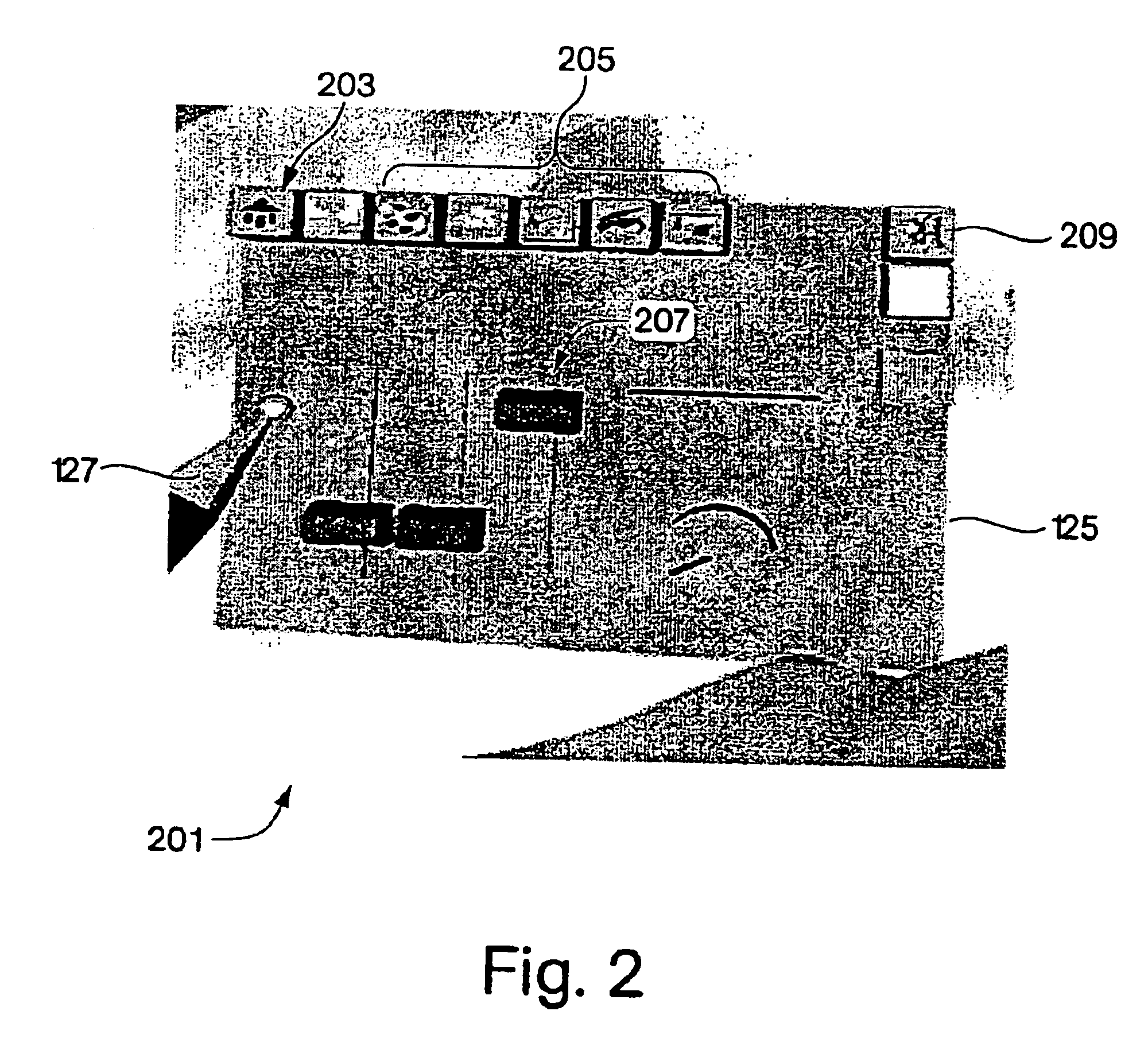
The pad and pen interface of the invention employs a transparent pad and a large, pen-shaped plastic tube that functions as a pen and is further equipped with a button that is used in the same fashion as a mouse button to activate an object selected by the pen. The interface is used with a virtual table, but can be advantageously employed in any virtual reality system that uses back projection to create at least part of the virtual environment. FIG. 1 shows a system 101 for creating a virtual environment on a virtual table 111 in which the pad and pen interface of the...


PUM


Abstract

The tools include components which are images produced by the system (103) that creates the virtual environment in response to inputs specifying the tool's location and the point of view of the tool's user. One class of the tools includes transparent components (121, 123); the image component of the tool is produced at a location in the virtual environment determined by the transparent component's location and the point of view of the tool's user. Tools in this class include a transparent pad (121) and a transparent stylus (123). The transparent pad (121) has an image component that may be used as a palette, as a magic lens, and as a device for selecting and transporting components of the virtual environment or even a portion of the virtual environment itself.

Description

BACKGROUND OF THE INVENTION1. Field of the InventionThe invention relates generally to tools by means of which users of an interactive environment may interact with the environment and more specifically to tools for interactively manipulating objects belonging to a virtual environment.2. Description of Related ArtWith the continuing increase in processor power and memory density and decrease in the cost of processors and displays, virtual reality systems, in which computers are used to generate displays that appear to the user to be three-dimensional, have become more than laboratory curiosities. Such displays are termed in the following virtual environments. A natural area of application for virtual environments would seem to be design: most objects are three-dimensional, and a computer-aided design (CAD) system that creates a virtual environment should be able not only to provide the designer with a three-dimensional representation of the object being designed, but should also be ...

Claims


Application Information

Patent Timeline
Patent Type & Authority Patents(United States)
IPC IPC(8): G06F3/033G06F3/00G06F3/01G06F3/042
CPCG06F3/011G06F3/017G06F3/04883G06F3/0346G06F3/033
Inventor SCHMALSTIEG, DIETERBIMBER, OLIVERENCARNACAO, L. MIGUEL
Owner FRAUNHOFER GESELLSCHAFT ZUR FOERDERUNG DER ANGEWANDTEN FORSCHUNG EV
Learn More