
Thermal printer with improved transport, drive, and remote controls

a printer and thermal technology, applied in the field of printers, can solve the problems of mechanical elements which although workable in some cases did not always provide the best, affecting the quality of printing, so as to reduce the variation of printing ribbons and achieve the effect of inconsistency in printing quality

Inactive Publication Date: 2005-01-11
TSC AUTO TECH
View PDF14 Cites 58 Cited by
  • Summary
  • Abstract
  • Description
  • Claims
  • Application Information

AI Technical Summary

Benefits of technology

In summation, this invention is a thermal printer, drive and transport system having rollers which help to remove plastic print ribbon inconsistencies from the spool while maintaining tension, proper movement, transport, and a smoothing effect to the print ribbon with a gimbaled or pivotal support for accommodating support across the width of the print ribbon. Additionally drive controls and motor functions are provided for improved ribbon and media drive with enhanced overall automatic control.
More specifically, the invention comprises a print ribbon transport and drive system which helps to remove ribbon inconsistencies and variations. Ribbon variations are encountered due to the fineness of the print ribbon and heating that takes place at the thermal printer head. In order to remove the variations this invention utilizes a pair of rollers or other offset surfaces. The rollers specifically work the print ribbon in one direction and then the reverse direction. This reversal of direction and the working of the print ribbon irons the print ribbon in a manner so that wrinkles are diminished.
The invention further incorporates the concept of eliminating variations by working the print ribbon over a roller or another type of reverse surface. This working can be enhanced by variable spring loadings on the ribbon through leaf coil springs or other means supporting rollers or other working surfaces such as rods or plates across which the print ribbon moves.
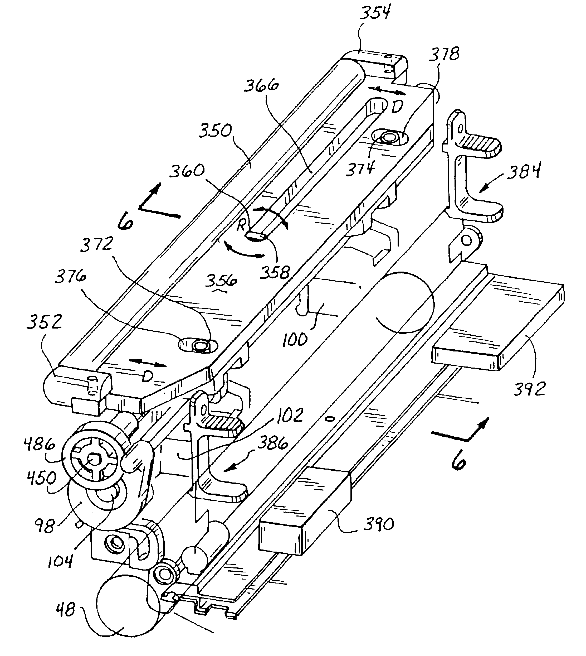
The invention enhances the further handling of the print ribbon after and during the movement thereof through the print head process by means of another transport system. This second transport system after printing incorporates a roller or guide surface which can be gimbaled to accommodate variations across the width of the print ribbon. This gimbaled roller can be provided with any other type of surface so as to accommodate the movement of the print ribbon thereacross.
As a consequence, this invention is a significant step with regard to the transport of print ribbon, the ability to diminish print ribbon variations, inconsistencies in print quality, and the ability to make adjustments of variably sized print ribbons.

Problems solved by technology

The print ribbon when passing under the heating element or printer head and on top of an underlying media and before and after is subject to wrinkling, striations, displacement, stretching, and other distortions.
These mechanical elements which although workable in some cases did not always provide the best results.
Also, there was generally no way to compensate for this on a remote basis and / or as a real time function.
Oftentimes, the print ribbons become mismatched with the underlying media, and distortions occur in a bar code which can be quite severe.

Method used


Image

  • Thermal printer with improved transport, drive, and remote controls
  • Thermal printer with improved transport, drive, and remote controls
  • Thermal printer with improved transport, drive, and remote controls

Examples


Embodiment Construction

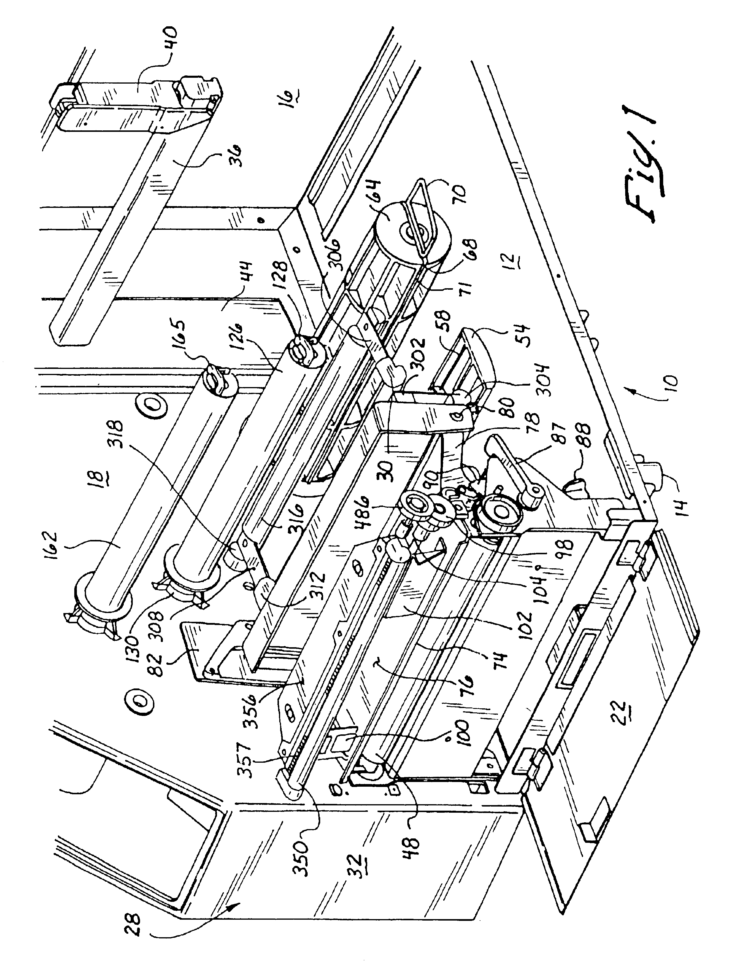
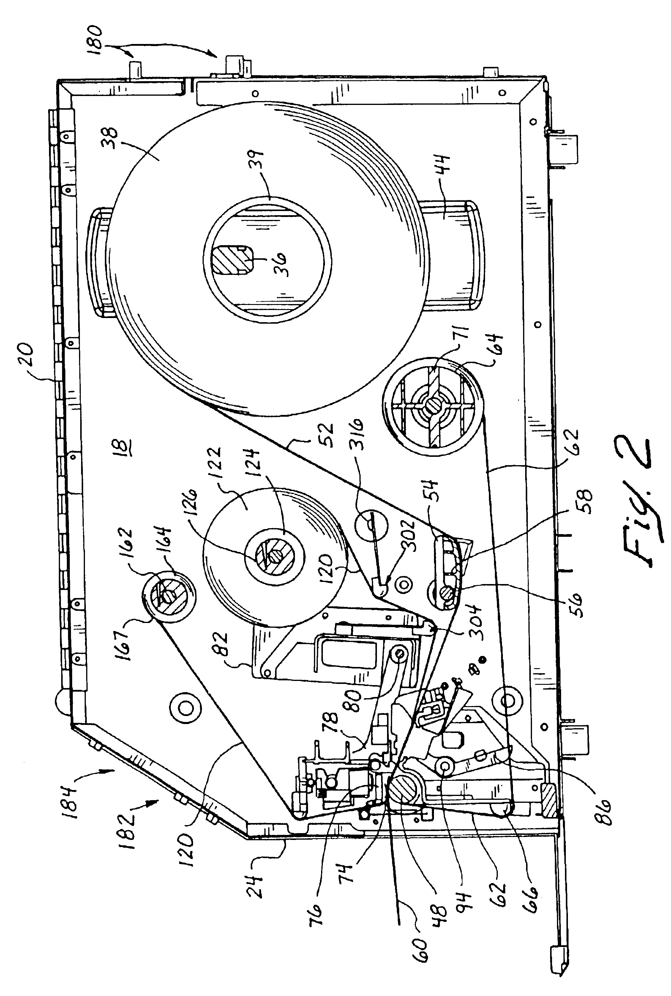
Looking more specifically at FIGS. 9 and 10, it can be seen that the thermal printer as an alternative embodiment of this invention is shown in a perspective and side elevation view. The perspective view of FIG. 9 does not have any print ribbon connected to the respective spindles nor any media on spools as in FIG. 10. FIG. 10 more aptly shows the path of the media and the print ribbon which shall be detailed hereinafter.

Looking at the apparatus of FIG. 9, it can be seen that a thermal printer 10 has been shown with a case constituting a base portion 12 having legs 14 upon which it stands. The base portion 12 forms the base for back wall 16 and cast drive support wall 18 that is in the form of a casting. The casting of wall 18 is specifically utilized because of the rigidity which is desired for the supports of the drive mechanism.

The casing is covered by a hinged lid that is not shown but wherein the hinges 20 attached to the lid are shown in FIG. 2. A frontal access door 22 and to...


PUM


Abstract

A thermal printer utilizing a platen on which media can move over a print head in association with print ribbon from a supply spool driven by motors connected to a print ribbon supply and take-up with a program to provide current settings and engine control to the ribbon. The printer further has a ribbon support, a program, and a processor connected to a drive for causing the drive to move the support in response to ribbon width. The printer has a control panel, a file system with current settings connected to the file system, and further includes engine control software for controlling the printer functions including print head pressure, print head temperature, and a ribbon support based upon the width of the print ribbon.

Description

BACKGROUND OF THE INVENTION1. Field of the InventionThis invention relates to printers which place a series of dots on underlying media to form a pattern, alpha numeric symbols, or a bar code. It relates more to those types of printers which are thermal printers wherein a print ribbon having a wax or other displaceable material thereon can be heated and disposed on an underlying media for printing thereon. Such underlying media can comprise paper, plastic, a web supporting a plurality of labels, or other media. The invention specifically relates to the print ribbon transport and drive control in a consistent manner to avoid various printing inconsistencies as well as an improved controller. Such printing inconsistencies can be light or dark print, improper alpha numeric symbols, or fuzzy printing as well as bar codes having either unclear or improper separations. This invention is in the field of the transport of the print ribbon, media, drive thereof, and control from a remote loca...

Claims


Application Information

Patent Timeline
IPC IPC(8): B41J2/325B41J33/14B41J33/34B41J33/52
CPCB41J2/325B41J33/52B41J33/34
Inventor BARRUS, GORDON B.WHITE, DENNIS R.MOORE, KEVIN P.
Owner TSC AUTO TECH
Learn More