
Pneumatic cable tie tool

Inactive Publication Date: 2005-01-11
PANDUIT
View PDF29 Cites 38 Cited by
  • Summary
  • Abstract
  • Description
  • Claims
  • Application Information

AI Technical Summary

Problems solved by technology

Most prior tools, though capable of tensioning and thereafter severing the excess tail portion of the cable tie, have several disadvantages associated therewith which, either singularly or plurally, increase the frequency of operator injuries, and increase the frequency and magnitude of tool degradation and failure.
A disadvantage of the cast metal body, however, is that it requires a significant number of manufacturing steps, driving the cost higher.
Additionally, a more deeply curved handle is shown, though in practice the foam handle cover used therewith yields a result which is not very ergonomic.
The major disadvantage of this tool is the combination of a high angular force linkage design and a plastic body.
Due to this combination, the tool is not nearly as durable as some previous designs.
Consequently, the uniform severance point that is normally achieved with the linkage style design becomes unpredictable, and accurate and consistent tensioning is not possible.
Ultimately such a tool will fail to produce reasonably repeatable results, after which the tool must be discarded.
In practice, the design has resulted in a poorly performing tool that is not durable, is subject to tensioning inconsistences between tools, fails to provide a distinct and uniform severance point, is unable to accurately calibrate its tension setting, and includes a fragile tension setting device.
Despite its advantages over many prior designs, however, the tool still requires manual power to tension the cable ties.
Additionally, this prior design utilizes many parts and thus has a somewhat higher manufacturing cost than other designs, particularly those using external power.

Method used


Image

  • Pneumatic cable tie tool
  • Pneumatic cable tie tool
  • Pneumatic cable tie tool

Examples


Embodiment Construction

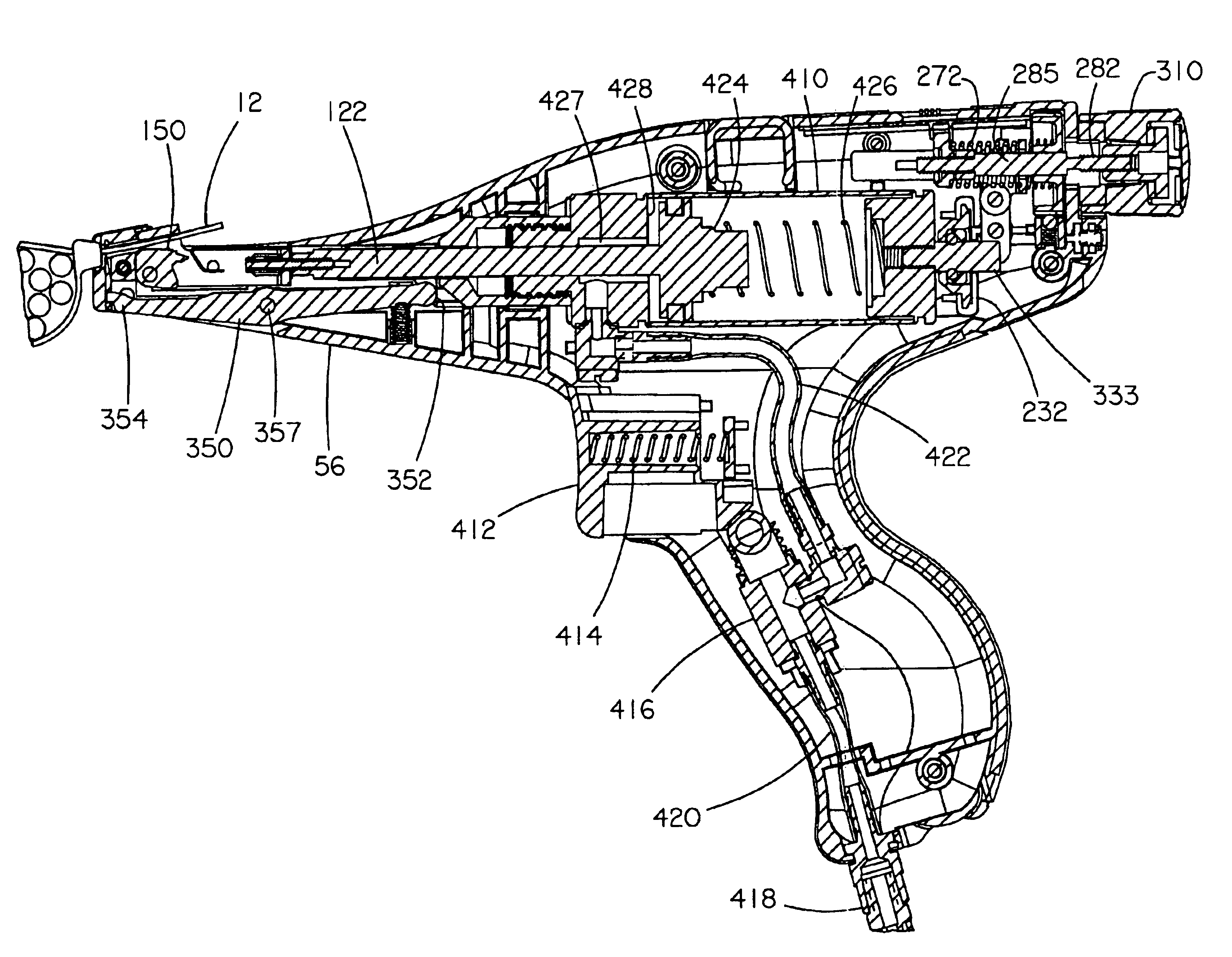
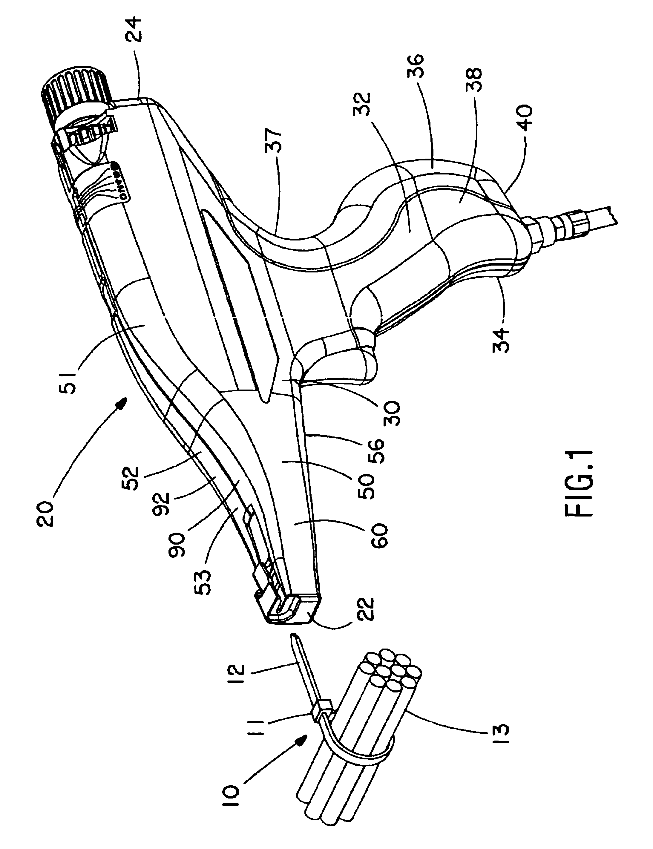
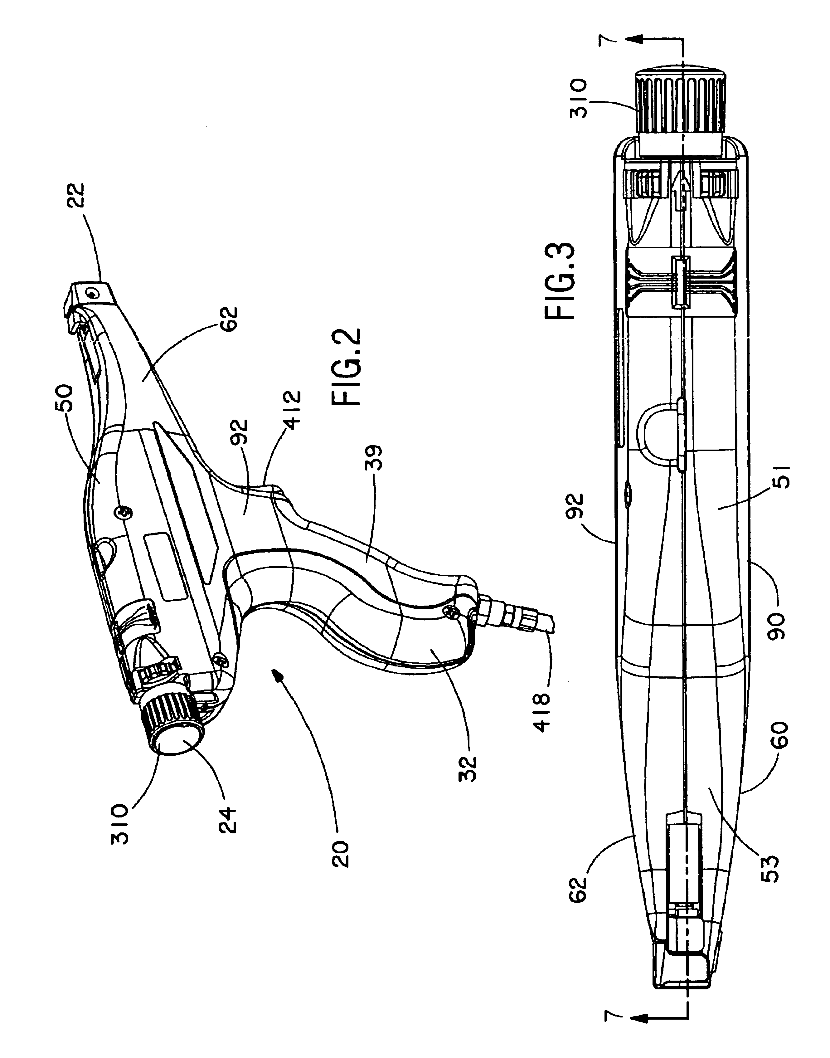
A tool for installing a cable tie embodying the present invention is designated generally by the reference numeral 20 in the accompanying drawings. As shown in FIGS. 1-3, the hand-held tool 20 has a housing 30 having a handle portion 32 and a barrel portion 50. The housing 30 includes two separate complimentary sidewall portions 90 (left) and 92 (right) that are secured together to define the handle portion 32 and the barrel portion 50. The handle portion 32 has a front 34, a back 36, opposite sides 38 and 39, and a bottom 40. In the illustrated embodiment, the sides 38 (left) and 39 (right) are generally arcuately shaped for ergonomic reasons and are substantially mirror images of one another. The back 36 is also correspondingly arcuately-shaped, including a deeply recessed portion 37 which enhances the ergonomics of the tool 20. The front 34 is also arcuately-shaped, however, less dramatically so than the back 36. The bottom 40 has a curvilinear surface joining the sides 38 and 39...


PUM

PropertyMeasurementUnit
Pressureaaaaaaaaaa
Tensionaaaaaaaaaa

Abstract

A tool for installing a cable tie, said cable tie having a head portion and an elongate tail portion extending therefrom, said tool comprising a housing having a distal end and a proximate end, a tensioning mechanism for tensioning said cable tie to a predetermined tension setting, said tensioning mechanism operatively supported by said housing, a cutting mechanism for severing an excess portion of said tail from said tensioned cable tie, said cutting mechanism operatively supported by said housing, a manually actuable external power delivery system for actuating said tensioning and cutting mechanisms, said power delivery system for delivering power generally in line with said tensioning mechanism, and a restraint mechanism for providing said predetermined tension setting wherein said restraint mechanism provides said predetermined tension generally in line with said tensioning mechanism and said power delivery system.

Description

BACKGROUND OF THE INVENTIONThe present invention relates generally to hand-held cable tie tensioning and severing tools, and more particularly, to an improved tool for reliably installing or applying high tension to flexible cable ties and severing the ends thereof without over-tensioning the cable ties.As is well known to those skilled in the art, cables ties are typically used to bundle or secure a group of elongated articles, such as electrical wires and cables. Cable ties of conventional construction include a cable tie head and an elongated tail extending therefrom. The tail is wrapped around a bundle of articles and thereafter inserted through a passage in the head. The head of the cable tie typically supports a locking element that extends into the head passage and engages the tail to secure the tail to the head, or at least prevent rearward travel of the tail back through the passage so as to disengage the head.In practice, the installer manually places the tie about the art...

Claims


Application Information

Patent Timeline
IPC IPC(8): B65B27/10B65B13/00B65B13/02B65B27/00
CPCB65B27/10B65B13/027
Inventor HILLEGONDS, LAWRENCE A.
Owner PANDUIT
Learn More