
Latching stair rod assembly

a technology for latching stair rods and brackets, which is applied in the field of latching stair rod bracket design, can solve the problems of obscuring the attached base, affecting the installation of mounting screws in the base portion, and difficulty in removing the stair rod, so as to facilitate the installation procedur

Inactive Publication Date: 2005-01-11
KAUFMAN BENJAMIN I
View PDF13 Cites 13 Cited by
  • Summary
  • Abstract
  • Description
  • Claims
  • Application Information

AI Technical Summary

Benefits of technology

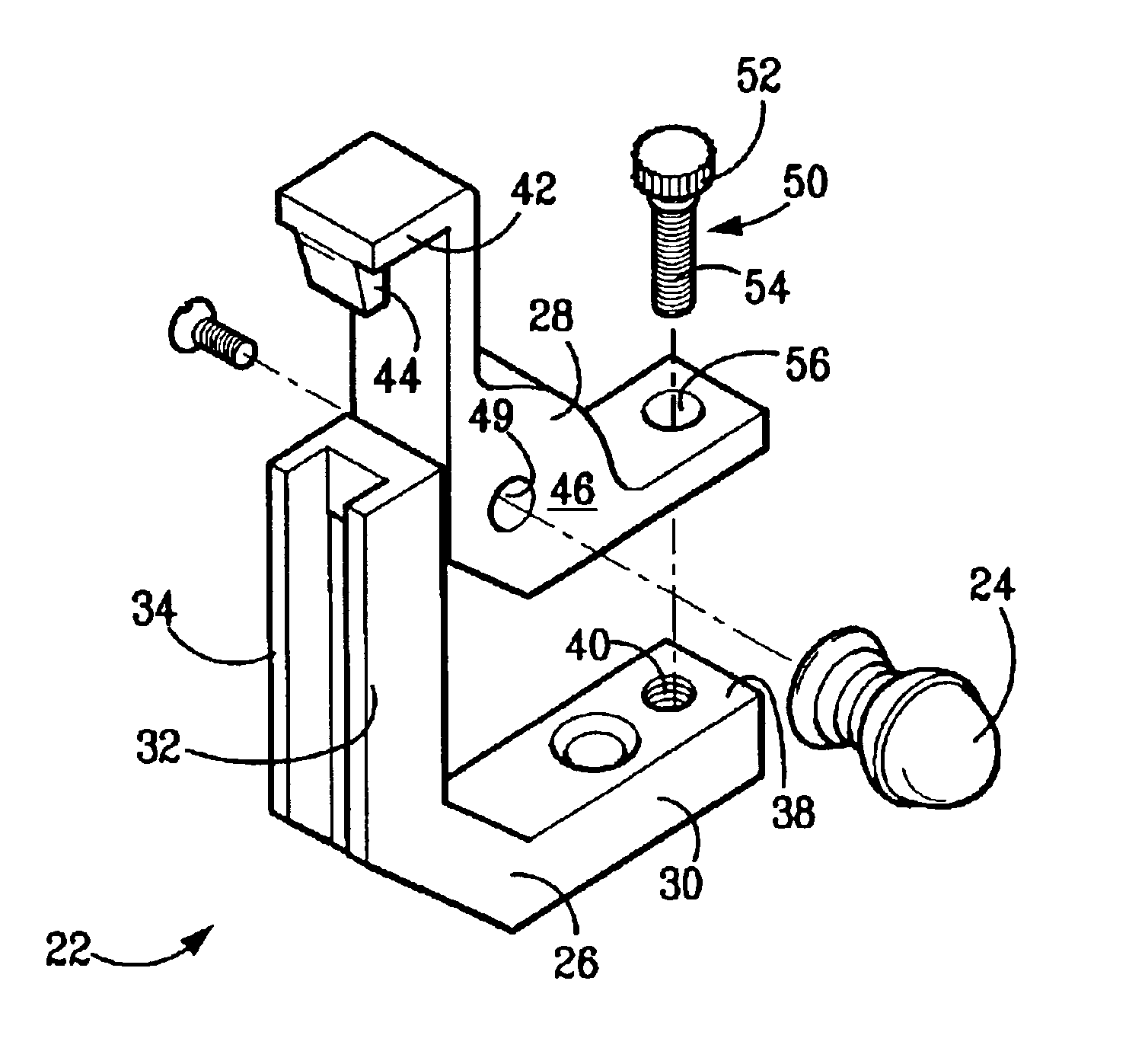
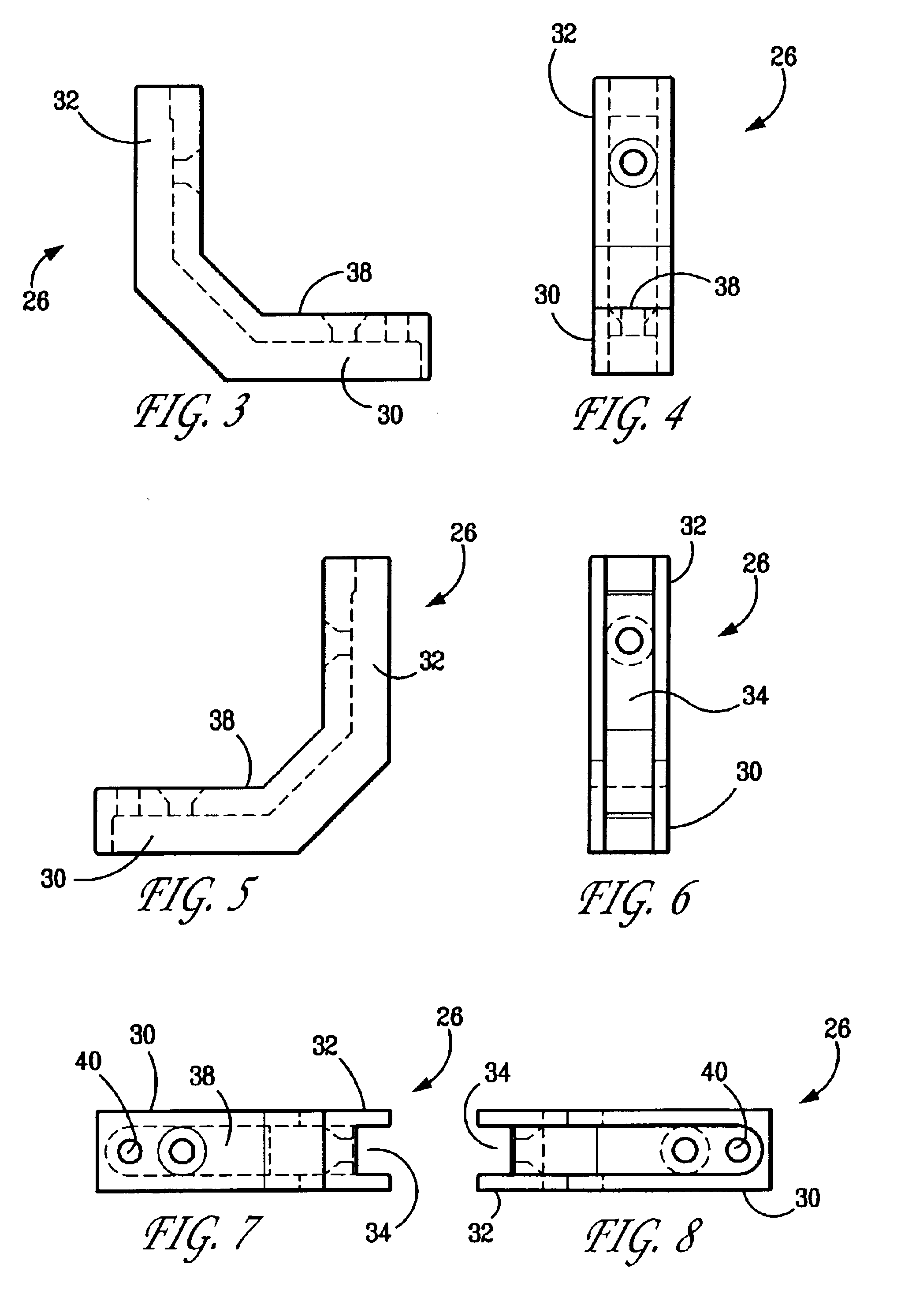
The present invention is directed to a latchable stair rod bracket design that facilitates the installation procedure and the assembly and disassembly of the brackets and the removal of the stair rod. In one embodiment of the present invention, a stair rod bracket comprises a separate mounting base component and upper bracket component. The mounting base is mounted to a stair riser and tread, preferably using two screws. In the mounting base there is an open channel groove and the upper bracket has a latch that latchably engages into the channel groove of the mounting base.

Problems solved by technology

A bracket having such hinge design is difficult to attach to the stair tread and corresponding riser because the top portion can be swung open only as far as the stair riser will allow, thus obscuring the attached base and interfering with the installation of the mounting screws in the base portion.
With this lateral slidable design, removal of the stair rod may be difficult due to minimal clearance between the bracket and the sidewall (or stair stringer) of the stair.
Further, with this design, it is not possible to slide the bracket away from the sidewall of the stairs because the stair rod and the bracket as thus designed prevent such movement.

Method used


Image

  • Latching stair rod assembly
  • Latching stair rod assembly
  • Latching stair rod assembly

Examples


Embodiment Construction

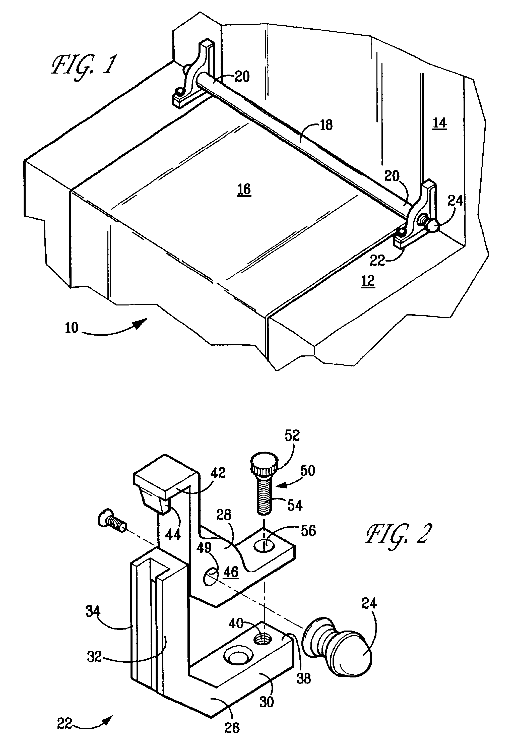
The present invention is directed to a latchable stair rod bracket design that facilitates the installation procedure and the assembly and disassembly of the stair rod bracket and the removal of a stair rod. FIG. 2 is a perspective view of a latchable stair rod bracket according to an embodiment of the present invention.

Carpeting, carpet runners and other floor covering are often used to cover the stairs of a staircase. Stair rods are frequently used, both for their decorative aspects, as well as their functional attributes in bearing against the covering on the stairs.

As shown in FIG. 1, a standard staircase 10 may have any number of steps or treads 12 connected by risers 14. The specific number of treads and risers will depend on the location and size of the staircase, as is well known. For illustrative purposes, a carpet runner 16 is shown in place, and is stretched to exactly cover the tread and risers, as is known in the industry.

Stair rods 18 are then used for both decorative ...


PUM


Abstract

A mounting base component and an upper bracket component comprise the stair rod bracket. The mounting base component is secured to the tread in any suitable manner and it includes an aperture or an open, elongate channel. The upper bracket component conforms to the shape of the mounting base component, so that, when they are mounted together, they define a single, integral bracket. Extending out from the upper bracket component is a latch that latchably engages into the opening or channel of the mounting base. A stair rod can be easily removed or installed by sliding the upper bracket to disengage it and then by lifting it away from the mounting base. Assembly and disassembly of a stair rod bracket according to the present invention is not impeded or made difficult by the framework of the stairs.

Description

FIELD OF THE INVENTIONThe present invention relates generally to the carpeting and hardware industries and, in particular, to a latching stair rod bracket design that facilitates installation and assembly of the stair rod brackets and stair rod, as well as the removal of a stair rod.BACKGROUND OF THE INVENTIONMany conventional stair rod bracket designs comprise hinged designs, where a top portion of the bracket is attached to a base portion via a hinge mechanism. A bracket having such hinge design is difficult to attach to the stair tread and corresponding riser because the top portion can be swung open only as far as the stair riser will allow, thus obscuring the attached base and interfering with the installation of the mounting screws in the base portion. Blackstone (U.S. Pat. No. 6,338,179) shows one such design.Another conventional stair rod bracket design is described in Zoroufy (U.S. Pat. No. 5,960,516), which is incorporated herein by reference. Generally, this stair rod bra...

Claims


Application Information

Patent Timeline
Patent Type & Authority Patents(United States)
IPC IPC(8): A47G27/06A47G27/00
CPCA47G27/065Y10T16/125Y10T16/10
Inventor KAUFMAN, BENJAMIN I.
Owner KAUFMAN BENJAMIN I
Learn More