Extension and locking assembly for dripless element, and container therefore
- Summary
- Abstract
- Description
- Claims
- Application Information
AI Technical Summary
Benefits of technology
Problems solved by technology
Method used
Image
Examples
second embodiment
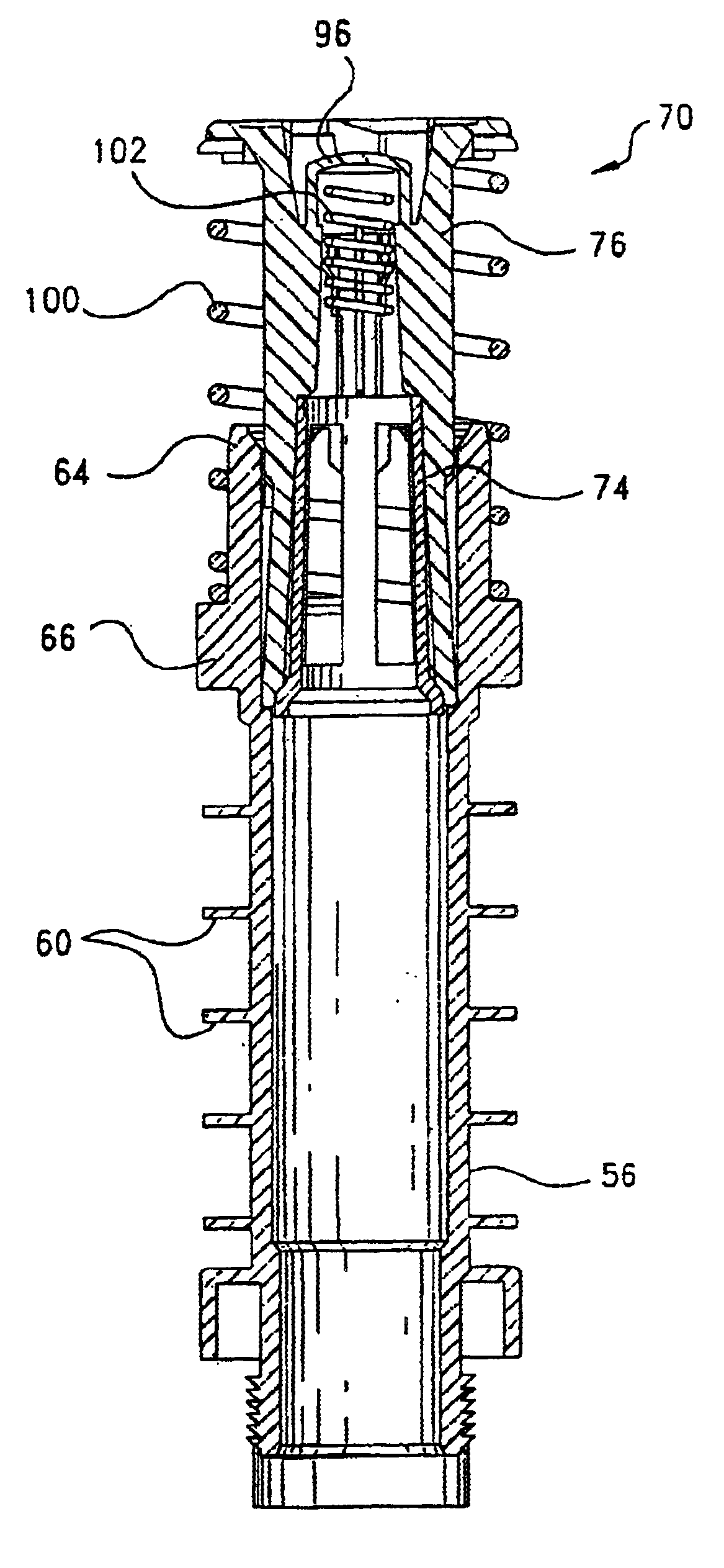
the extension and locking assembly 70 is illustrated in FIGS. 10 and 11. In this embodiment, the bypass feature is provided by a separate valve component, indicated generally at 144. Valve component 144 operates in the same manner as the bypass valve described above, and includes a body 146; an enlarged valve head 148; and a pair of elongated and axially-extending fingers 150, each of which have a catch 152 at their distal ends. The body 146 of the valve component is received in a circular opening defined by an annular support 154 in the locking member, with the catches 152 engaging the support 154 to prevent the valve component from being removed from locking member 74. Bypass spring 102 extends between the head 148 of the valve component and an inner annular shoulder 155 of the bypass member, and urges valve component 144 outwardly from the support core.
The enlarged annular head is absent from the locking member 74 illustrated in FIG. 11. Instead, the valve head 148 and the catche...
PUM
| Property | Measurement | Unit |
|---|---|---|
| Length | aaaaa | aaaaa |
| Diameter | aaaaa | aaaaa |
| Distance | aaaaa | aaaaa |
Abstract
Description
Claims
Application Information
 - R&D
- Intellectual Property
- Life Sciences
- Materials
- Tech Scout
- Unparalleled Data Quality
- Higher Quality Content
- 60% Fewer Hallucinations
Browse by: Latest US Patents, China's latest patents, Technical Efficacy Thesaurus, Application Domain, Technology Topic, Popular Technical Reports.
© 2025 PatSnap. All rights reserved.Legal|Privacy policy|Modern Slavery Act Transparency Statement|Sitemap|About US| Contact US: help@patsnap.com


