
Electroacoustic transducer

a transducer and electroacoustic technology, applied in the direction of electrical transducers, transducer details, selectrostatic transducers, etc., can solve the problems of difficult stable manufacture of electroacoustic transducers, carrier cannot keep its flatness, and greatly limited amplitude so as to reduce the influence of external forces and increase the amplitude of the diaphragm in response to sound waves

Inactive Publication Date: 2004-10-12
RION COMPANY
View PDF11 Cites 5 Cited by
  • Summary
  • Abstract
  • Description
  • Claims
  • Application Information

AI Technical Summary

Benefits of technology

is to provide an electroacoustic transducer, characterized in that the desirable tension of a diaphragm is not changed over time, the interval between the diaphragm and the electrode portion can accurately be kept or maintained over time, the amplitude of the diaphragm in response to sound waves can be increased, and the influence of an external force can be reduced.

Problems solved by technology

However, as for such a diaphragm clamped on a frame-shaped carrier having inwardly-extending supporting portions, the amplitude in response to sound waves is greatly limited compared to a case of no supporting portions because the supporting portions are a point where the vibration of the diaphragm is initiated.
In addition, since the carrier is a rectangular shaped frame body, there is a problem that the carrier cannot keep its flatness due to a strain or twist which is applied thereto along the diagonal.
Such a problem has an undesirable influence on the tension of the diaphragm or the interval between the diaphragm and the electrode portion.
Therefore, since it is necessary to prevent the carrier from being subject to a strain or twist at the time of assembling an electroacoustic transducer, the stable manufacture of an electroacoustic transducer is difficult.

Method used


Image

  • Electroacoustic transducer
  • Electroacoustic transducer
  • Electroacoustic transducer

Examples


Embodiment Construction

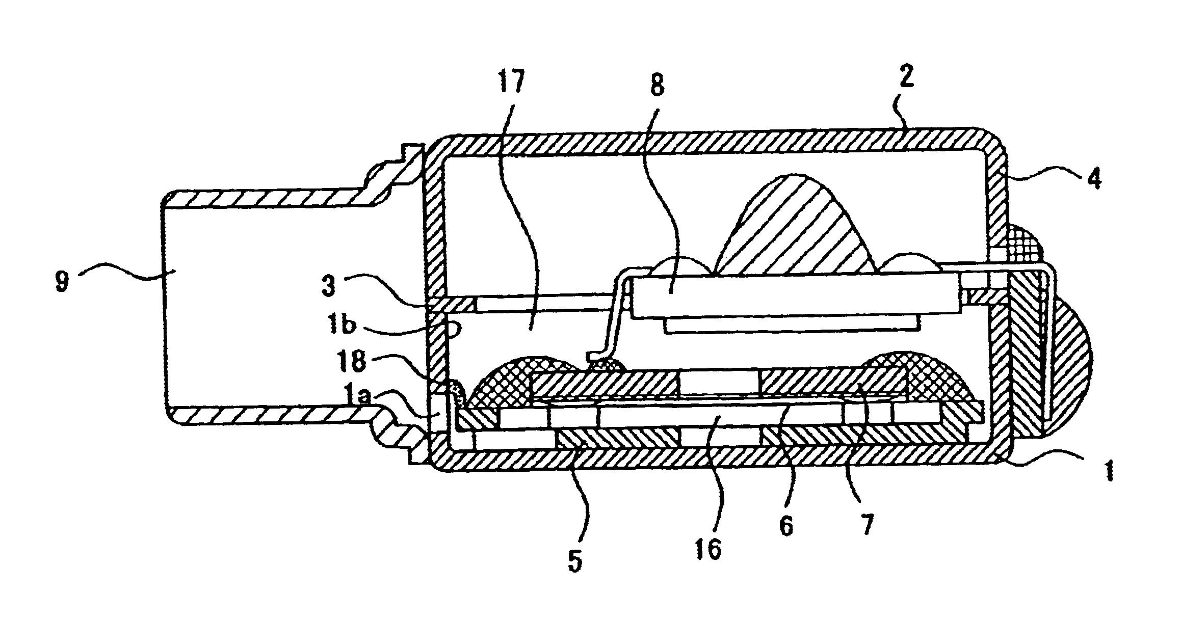
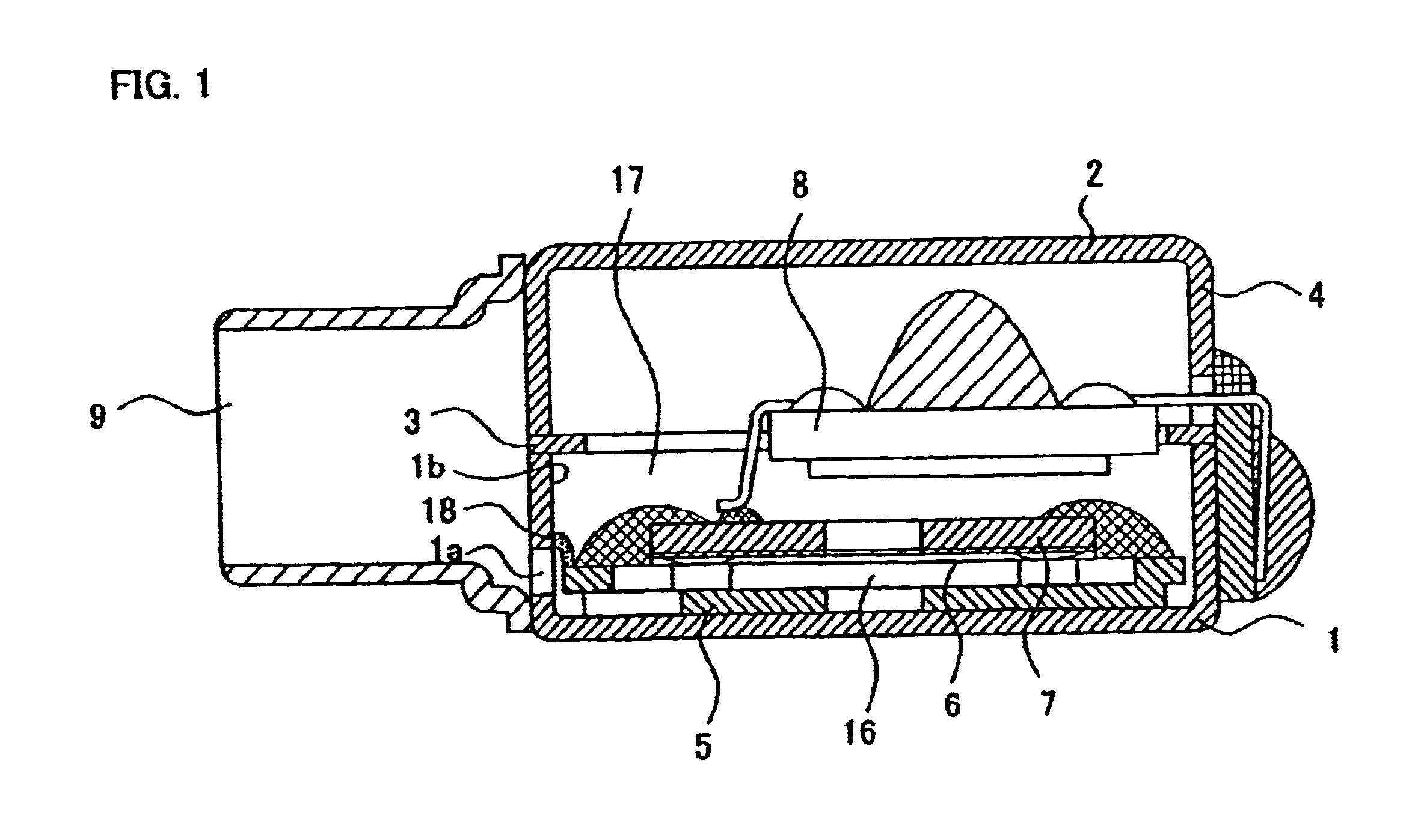
As shown in FIG. 1, in an electroacoustic transducer according to the present invention, a housing 4 is formed by interposing a frame member 3 between a case member 1 and a cover member 2. The housing 4 accommodates a diaphragm 6 and an electrode portion 7 fixed to a carrier portion 5. Reference numeral 8 refers to an amplifier and reference numeral 9 refers to a sound inlet opening.

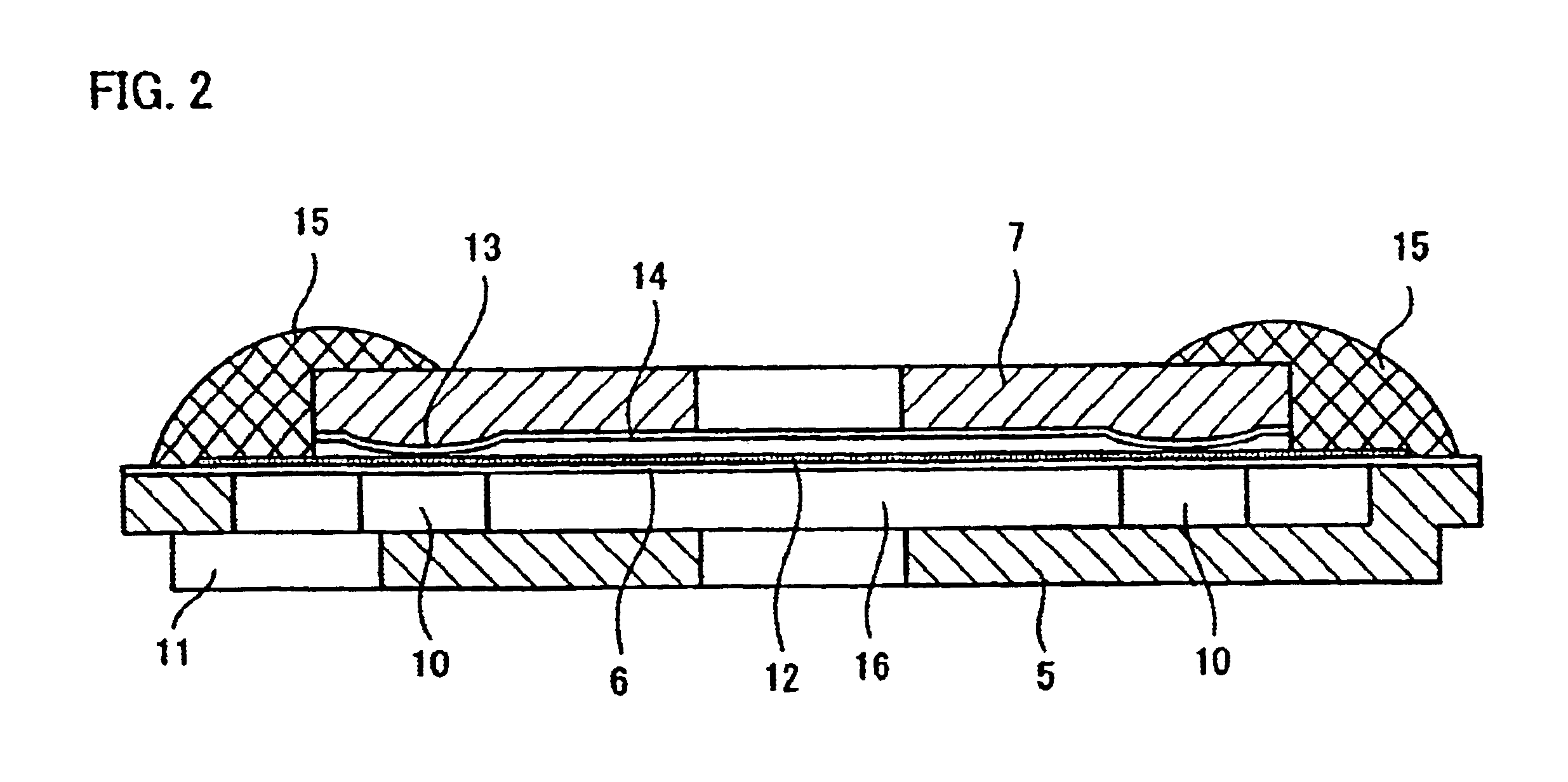
As shown in FIGS. 3 and 4, the carrier portion 5 is formed in a rectangular saucer-like shape, having a central recess defined above a bottom surface 5a and surrounded by a periphery, which is accommodated in the case member 1. In the four corners of the bottom surface 5a of the carrier portion 5, there are provided upstanding posts 10 in an island-like pattern, and the upper surface 5b of the periphery of the carrier portion 5 and the end surfaces 10a of the posts 10 are formed in the same plane. Reference numeral 11 refers to a sound guide port 11 for guiding sound waves. Since the carrier portion 5 is...


PUM


Abstract

An electroacoustic transducer comprises a carrier portion, a diaphragm supported by the carrier portion, an electrode portion opposed to the diaphragm at a predetermined interval, and a housing accommodating the diaphragm and the electrode portion, wherein the carrier portion has a saucer-like shape, at the bottom surface of which a plurality of upstanding posts are provided, and wherein the upper surface of the periphery of the carrier portion and the upper end surfaces of the posts are in the same plane, the diaphragm is bonded to the surface of the periphery of the carrier portion and the end surfaces of the posts, and the electrode portion is fixed to the end surfaces of the posts which are covered by the diaphragm with spacers interposed therebetween.

Description

1. Technical FieldThe present invention relates to an electroacoustic transducer in which a diaphragm supported by a carrier portion and an electrode portion opposed to the diaphragm at a predetermined interval are accommodated in a housing, such as a microphone for use in a hearing aid or the like.2. Background ArtAs a conventional microphone for use in a hearing aid, as disclosed in U.S. Pat. No. 6,169,810 B1, there has been known an electroacoustic transducer in which a diaphragm having a conductive layer and an electrode portion having an electret layer are accommodated in a housing in a state where the electrode portion is opposed to the diaphragm at a predetermined interval by clamping the diaphragm on a frame-shaped carrier having inwardly-extending supporting portions and placing the electrode portion on the supporting portions with spacers interposed therebetween.However, as for such a diaphragm clamped on a frame-shaped carrier having inwardly-extending supporting portions...

Claims


Application Information

Patent Timeline
Patent Type & Authority Patents(United States)
IPC IPC(8): H04R19/00H04R19/01H04R25/00H04R17/00
CPCH04R19/01H04R19/016H04R25/00
Inventor YAMASAKI, TAKASHIKIDOKORO, KENICHI
Owner RION COMPANY
Learn More