
Method and system for generation of multiple viewpoints into a scene viewed by motionless cameras and for presentation of a view path

a motionless camera and view path technology, applied in the field of video image processing, can solve the problems of difficult synchronization of each of the moveable cameras and the alignment of images from the cameras, the mechanical actuator mechanism is expensive, and the delicate nature of the process

Inactive Publication Date: 2004-05-25
DIGIMEDIA TECH LLC
View PDF4 Cites 263 Cited by
  • Summary
  • Abstract
  • Description
  • Claims
  • Application Information

AI Technical Summary

Problems solved by technology

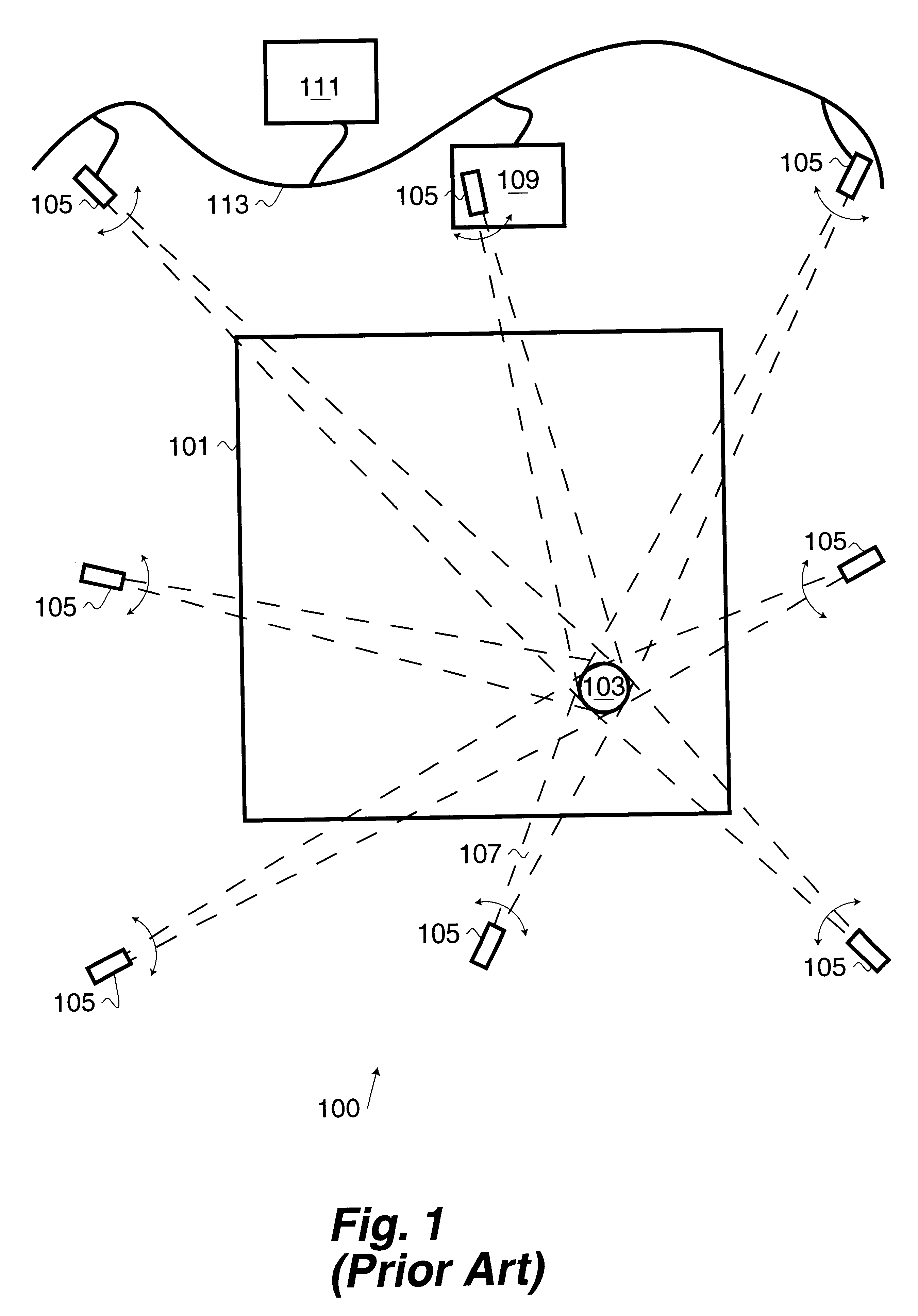
Some of the disadvantages of the prior art are that mechanical actuator mechanisms are expensive, delicate, require sufficient unobstructed space around the camera so as to move the camera and lens, are large enough to obstruct a viewer's view into the defined scene 101 (if the camera is between the viewer and the area-of-interest 103), and are unable to follow the area-of-interest 103 if it moves sufficiently rapidly through the defined scene 101.
In addition, it is very difficult to synchronize each of the moveable cameras and to align the images from the cameras.
The mechanical aspects of the PTZ cameras result in small mismatches in the view received by each of the cameras.
This mismatch requires that (for some special effects such as the viewpoint pan) the video processor (or computer) that receives the frames from each of the cameras must align and otherwise connect the frames.
In addition, vibrations (such as environmental vibrations and / or vibrations of the operation of the PTZ camera) often cause the mechanical features to become out of alignment.
Another disadvantage with PTZ cameras is that to track a rapidly moving area-of-interest 103 these cameras must be placed sufficiently far from the scene so that the area-of-interest stays within the field of view of the PTZ camera as it moves.
This placement of the camera far from the scene limits the ability to provide an "up-close" viewpoint of the area-of-interest even with zoom.
Furthermore, the noise and motion of a PTZ camera can be distracting when placed close to the scene.

Method used


Image

  • Method and system for generation of multiple viewpoints into a scene viewed by motionless cameras and for presentation of a view path
  • Method and system for generation of multiple viewpoints into a scene viewed by motionless cameras and for presentation of a view path
  • Method and system for generation of multiple viewpoints into a scene viewed by motionless cameras and for presentation of a view path

Examples


Embodiment Construction

One aspect of the invention is an improvement to the multiple moveable camera configuration 100 shown in FIG. 1. This improvement uses a novel combination of existing technologies to address the problems previously discussed with respect to FIG. 1 (as well as other problems).

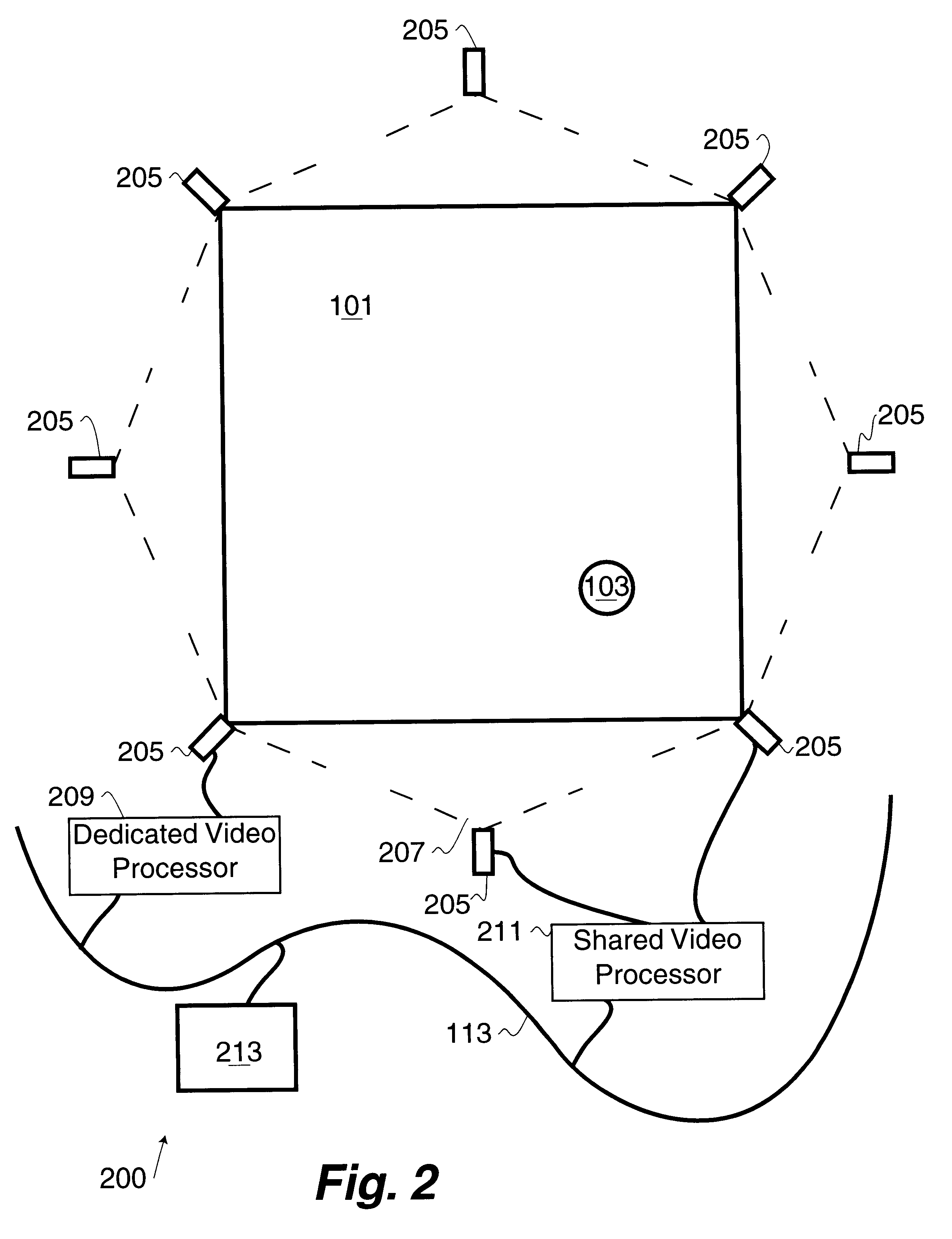
FIG. 2 illustrates a symmetrical stationary-camera configuration 200 as applied to the defined scene 101. In the symmetrical stationary-camera configuration 200, the area-of-interest 103 is tracked by stationary cameras 205 each having a field-of-view 207. The field-of-view 207 is sufficiently wide such that the entirety of the defined scene 101 is within the field-of-view 207. Using this configuration, the area-of-interest 103 is always within the field-of-view 207 of each of the stationary cameras 205. Each of the stationary cameras 205 is connected to either a dedicated video processor 209 or a shared video processor 211 that are in turn connected to a computerized controller 213 by the network 113. For clari...


PUM


Abstract

Methods and apparatus for defining a view path through at least one wide-angle video stream and for creation of a resultant unwarped video stream responsive to the view path. Aspects of the invention allow an operator to monitor the wide-angle video stream(s) and select which portion of the wide-angle frame to unwarp in real-time. Further, the operator can stop the playback of the wide-angle video stream and dwell within a particular wide-angle frame to create special effects such as camera tilt, pan and zoom operations in a stop action situation.

Description

1. Field of the InventionThis invention relates to the field of video image processing.2. BackgroundIt is known in the art how to use multiple video cameras to capture multiple viewpoints of a scene and to either select a desired video viewpoint of the scene or to recreate a desired video viewpoint from a model of the scene (the model created from information gathered by the captured multiple viewpoints of the scene) (see, for example, U.S. Pat. No. 5,745,126 entitled Machine synthesis of a virtual video camera / image of a scene from multiple video cameras / images of the scene in accordance with a particular perspective on the scene, an object in the scene, or an event in the scene, by Jain et al. and U.S. Pat. No. 5,850,352 entitled Immersive video, including video hypermosaicing to generate from multiple video views of a scene a three-dimensional video mosaic from which diverse virtual video scene images are synthesized, including panoramic, scene interactive and stereoscopic images...

Claims


Application Information

Patent Timeline
IPC IPC(8): G06T17/40H04N5/77
CPCG06T19/003H04N5/772G06T15/205
Inventor FURLAN, JOHN L. W.DRISCOLL, JR., EDWARD C.HOFFMAN, ROBERT G.FLUKER, DEREKBECHTEL, KAREN L.SHIFFER, KATERINA L.GARIMELLA, VENUGOPALCURTIS, DANIEL B.
Owner DIGIMEDIA TECH LLC
Learn More