
Method and apparatus for quantifying progress of sample clean up with curve fitting

a curve fitting and curve technology, applied in seismology for waterlogging, fluorescence/phosphorescence, instruments, etc., can solve the problems of wasting rig time, affecting the accuracy of sample cleanup,

Inactive Publication Date: 2004-03-30
BAKER HUGHES INC
View PDF3 Cites 50 Cited by
  • Summary
  • Abstract
  • Description
  • Claims
  • Application Information

AI Technical Summary

Problems solved by technology

On the other hand, if by pumping for very long time, it is possible to achieve only slightly better contamination level, an operator ends up wasting very expensive rig time and also risks the very costly possibility of allowing a tool to become stuck in the wellbore.
Another problem with monitoring sample clean up over time by looking at optical absorption over time is that sand particles and other particulates can cause considerable scattering, which causes the absorption values measured over time to "jump" and appear noisy.
If the projected time or volume required to reach that asymptotic value is determined to be excessive, the operator may abandon extracting fluid from the formation region.

Method used


Image

  • Method and apparatus for quantifying progress of sample clean up with curve fitting
  • Method and apparatus for quantifying progress of sample clean up with curve fitting
  • Method and apparatus for quantifying progress of sample clean up with curve fitting

Examples


Embodiment Construction

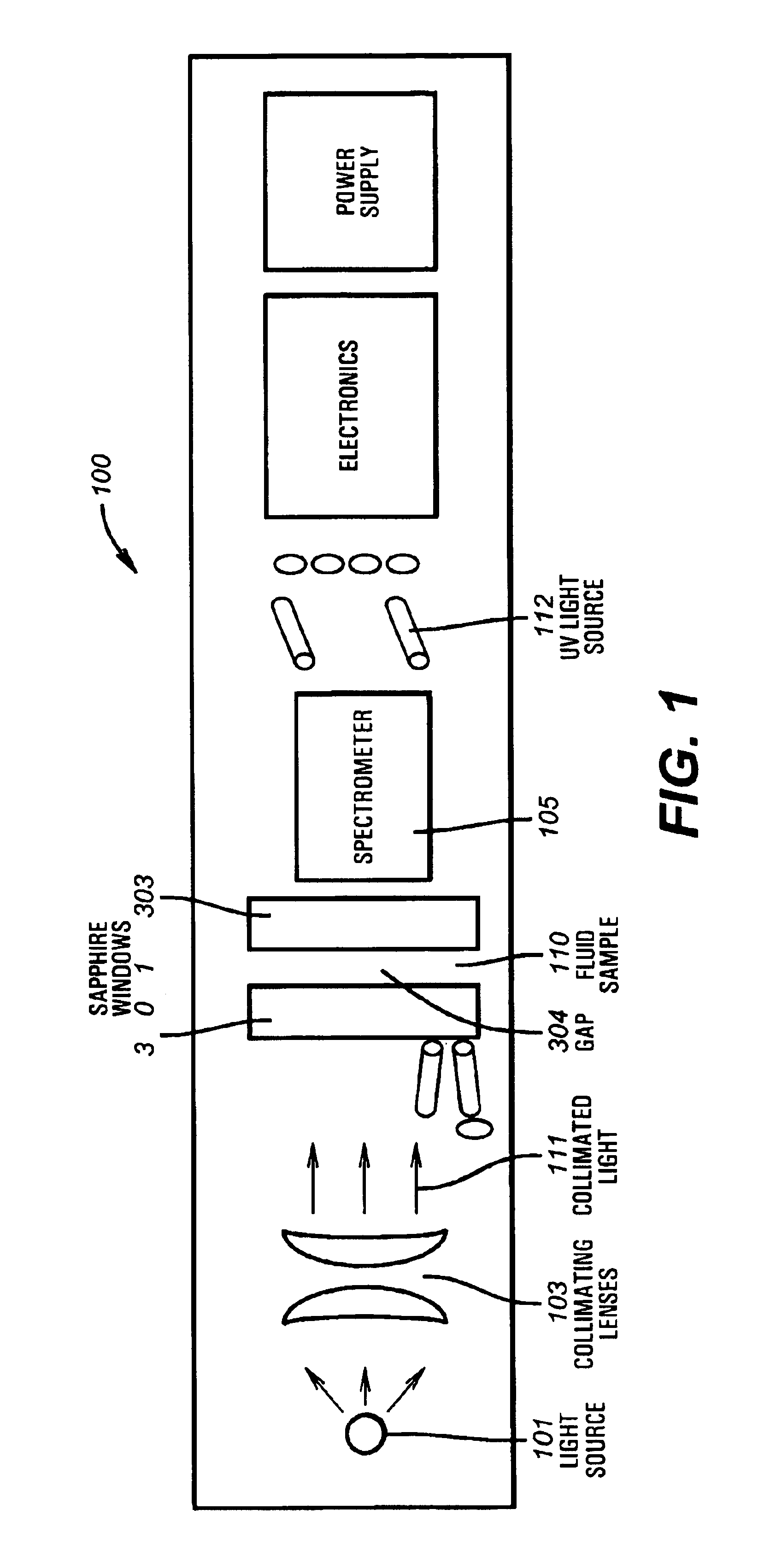
FIG. 1 illustrates a schematic representation for a downhole fluid characterization module, as, for example, the Baker Atlas SampleView.SM. tool. FIG. 10 is an illustration of the present invention 100 deployed form the Earth surface 15 in a borehole 12 from a wireline or drill string 18 sampling 14 a formation 16. In FIG. 1, A light source 101 (e.g. tungsten light bulb) emits light toward a sample 110, and this light is collimated by a collimating lens device 103 lying between the light source and the sample 110. The collimated light 111 is incident generally perpendicular to a first sapphire window 301 adjacent sample 110. Sapphire windows 301 and 303 lie generally perpendicular to the collimated beam of light and are separated by a gap or channel 304 enabling a fluid sample 110 to flow between them. Reflected and fluoresced light can be monitored over time in the spectrometer 105 to determine sample properties. The existing tools (FIG. 1) can be fitted with a UV light source 112,...


PUM

PropertyMeasurementUnit
depthaaaaaaaaaa
depthaaaaaaaaaa
invasion depthaaaaaaaaaa

Abstract

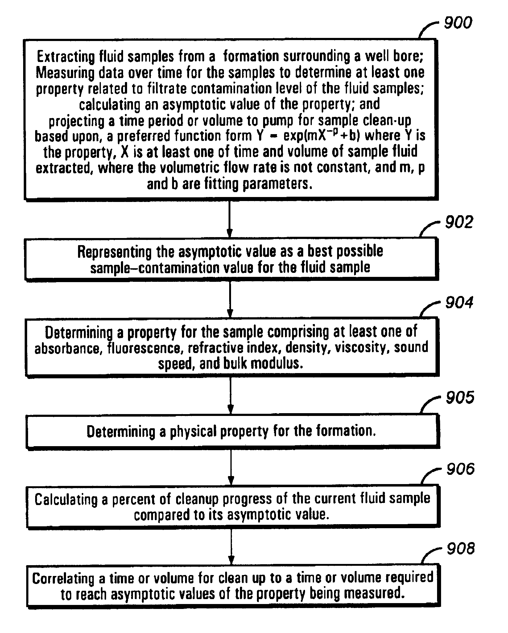
The present invention provides method of quantifying sample clean up in real time by providing curve-fitting measurements of optical or physical properties of fluid samples in boreholes. Sample fluid is extracted from the formation surrounding the borehole. As fluid continues to be extracted the composition of the extracted sample changes, altering the values of physical properties of the sample being measured. Measurements are made of optical or physical properties of the sampled fluid, and regression analysis is performed on the acquired measured data points. In one embodiment of the invention, iterative methods enable a user to determine an asymptotic value of a physical property, i.e. absorbance, as well as the percent of the progress that the current sample has obtained toward reaching the asymptotic property value and a projected time to reach the asymptotic property value. If the projected time required to reach that asymptotic value is too long, the operator may decide to abandon extracting fluid from the region. In another embodiment, a more general method enables the user to estimate, through the value of a variable, the speed at which cleanup can occur. The physical properties of the sample may be fit as a function of pumping time or volume.

Description

COPYRIGHT NOTICEA portion of the disclosure of this patent document contains material to which the claim of copyright protection is made. The copyright owner has no objection to the facsimile reproduction by any person of the patent document or the patent disclosure, as it appears in the U.S. Patent and Trademark Office file or records, but reserves all other rights whatsoever.Field of the InventionThe invention relates generally to a method for quantifying sample cleanup in real time in a wellbore environment. Specifically, the invention is a method of curve-fitting measurements of physical properties measured for fluid samples being pumped from a formation surrounding a wellbore by a wireline or monitoring while drilling formation tester to predict the time at which a sample having a desired purity can be obtained.Background of the InventionIn wellbore exploration, typically drilling muds such as oil-based muds and synthetic-based muds or water-based muds are used. The filtrates f...

Claims


Application Information

Patent Timeline
Patent Type & Authority Patents(United States)
IPC IPC(8): G01N33/26G01N33/28G01N21/64G01N21/53G01N21/47G01N21/41
CPCG01N33/2823G01N21/41G01N21/534G01N21/64G01N21/6428
Inventor DIFOGGIO, ROCCOLEE, JAEDONG
Owner BAKER HUGHES INC
Learn More