
Anti-pinch knuckle for bidirectional sleeve

a technology of anti-pinch knuckle and bi-directional sleeve, which is applied in the direction of roofs, special-purpose vessels, vessel construction, etc., can solve the problems of requiring a quick and sure manual collapse/deployment, requiring skilled users familiar with such sleeves to fail to properly latch out the bi-directional sleeve sliding, and structural failure becoming imminen

Inactive Publication Date: 2004-03-30
LEMOLE JOHN M
View PDF7 Cites 47 Cited by
  • Summary
  • Abstract
  • Description
  • Claims
  • Application Information

AI Technical Summary

Benefits of technology

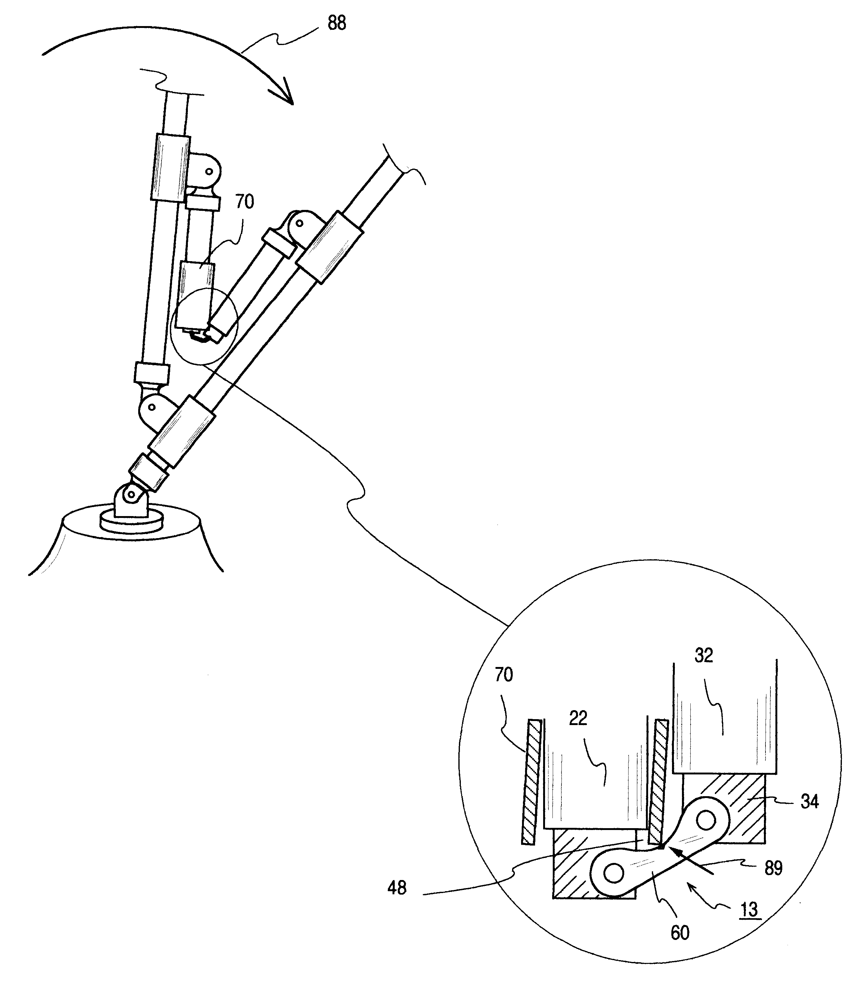
It is an object of the invention to provide a strut with a bidirectional slidable locking sleeve that will not become pinched at the folding joint.
It is an object of the invention to a provide an efficient lockable strut with a slidable sleeve cooperating with two spring loaded ball detents and joint structure which avoid sleeve pinching.
It is an object of this invention to allow collapsing and folding of marine coverings without removal of canvas and free of sleeve pinching at strut joints.

Problems solved by technology

Such coverings often are subject to wind and nature's violence and thus require a quick and sure manual collapse / deployment under adverse conditions.
Even skilled users familiar with such coverings may fail to properly latch out the sliding bidirectional sleeve and structural failure become imminent.
Indeed, on a pitching marine craft in extreme weather, it seems as if there are not enough hands to either properly set up or collapse such a covering.
In some folding instances, the slidable locking sleeve could become caught at the knuckle / joint location as the strut folds upon itself; and if that "catch" is not eliminated the leverage arms in the strut section may cause considerable structural damage.
Pinch potential may be the result of an accident, oversight or error in usage.

Method used


Image

  • Anti-pinch knuckle for bidirectional sleeve
  • Anti-pinch knuckle for bidirectional sleeve
  • Anti-pinch knuckle for bidirectional sleeve

Examples


Embodiment Construction

)

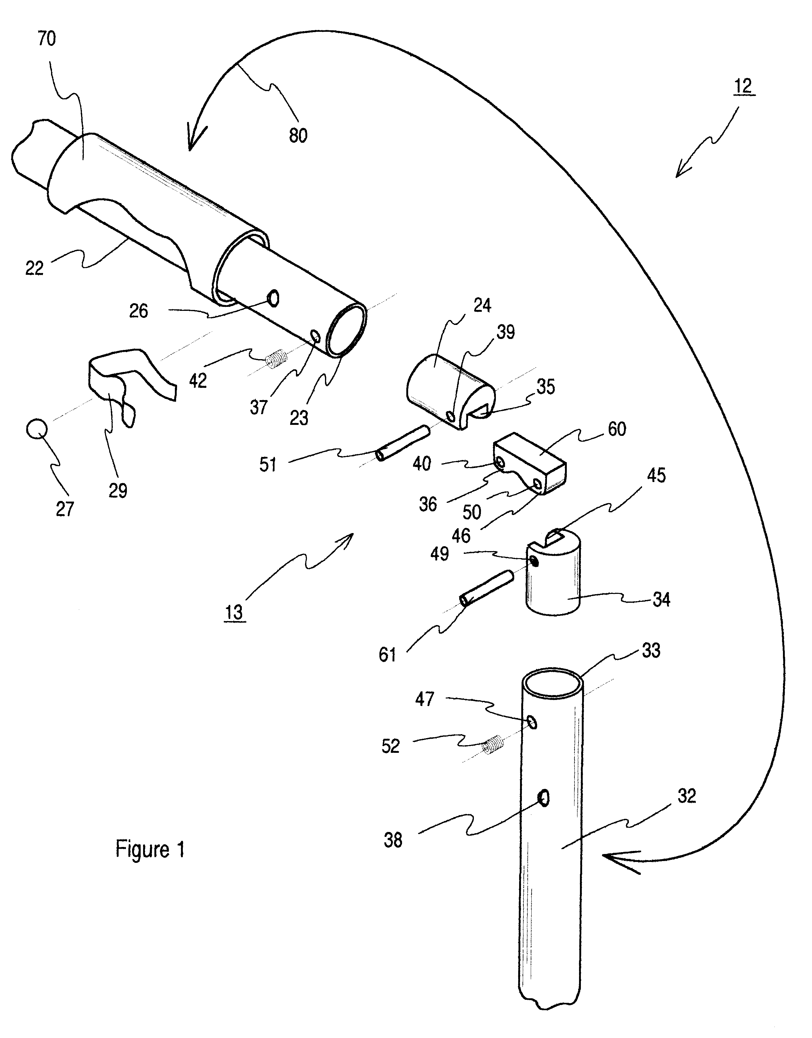
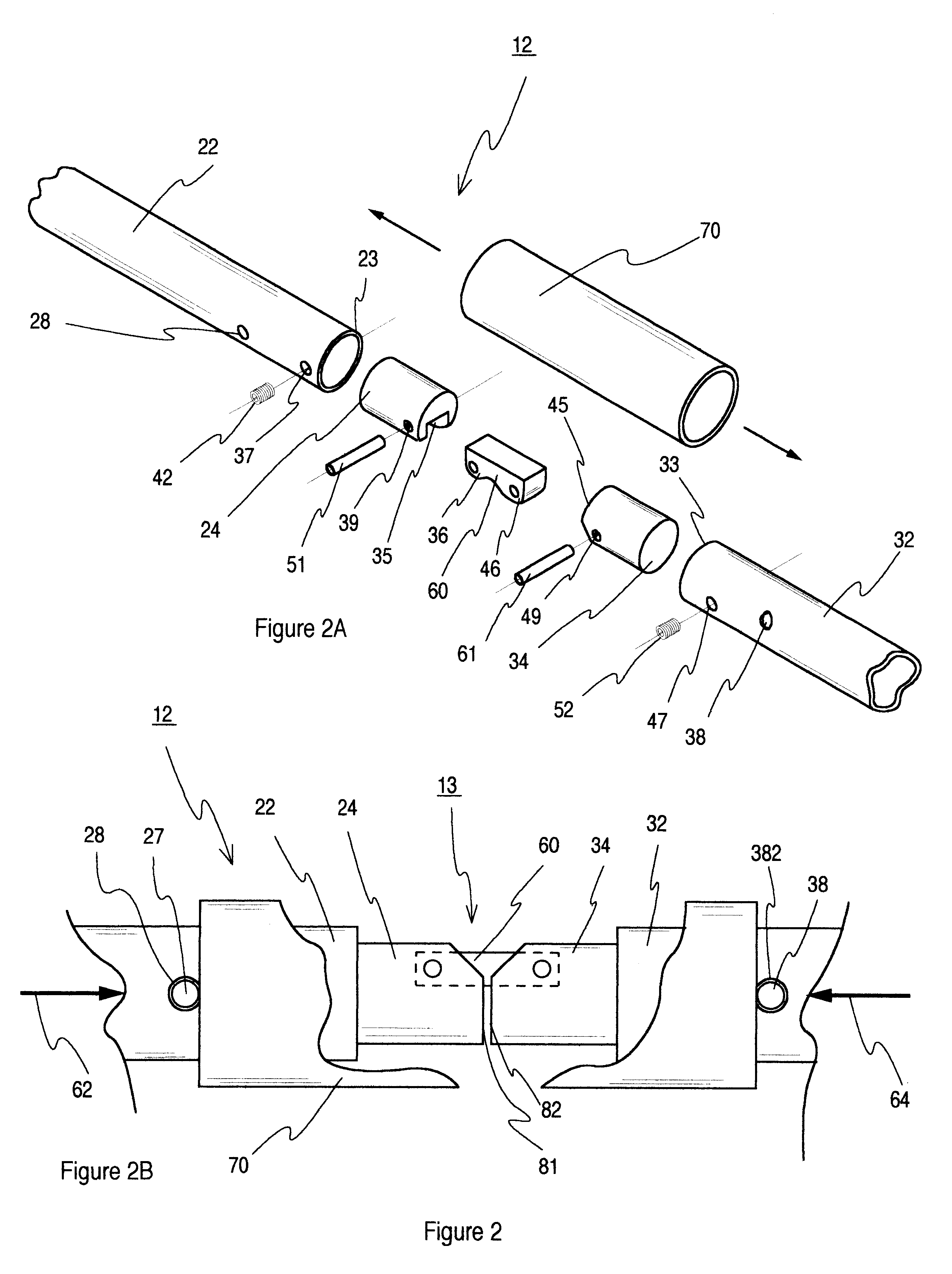
Turning now to FIG. 1, a preferred embodiment of my foldable strut is shown in exploded view. Foldable strut 12 is comprised of two strength member legs 22 and 32. Although various materials may be used, in its preferred embodiment, I have found stainless steel tubing in the range of one inch outside diameter to be a good choice for the strength members.

Adjacent inboard ends 23 and 33 are each permanently fitted with a pair of identical hubs 24 and 34. These hubs are identical in shape and function, and are secured to leg ends 23 and 33 via set screws 42 and 52. These inserts may be either injection molded, machined material such as Delrin, or even stainless steel hubs on conditions I will further describe later herein. An all stainless steel strut model is particularly acceptable--indeed, almost mandatory--to the marine industry.

Various new synthetic materials are readily available for fitting within stainless tubing members 22 and 32. When such mixed materials are involved, howev...


PUM


Abstract

An articulating strut capable of assuming an extended in-line and a folded configuration with rigid cylindrical tubing having proximate ends configured to fixably receive an offset hinged insert that provides for folding and unfolding of said strut. When fully unfolded the strut acts as a single rigid structural support member held in the locked position by a bidirectional slidable locking sleeve. The hinged insert has shapes and curved surfaces which together with offset hinge pins tends to expel the sleeve from a pinch possibility at the folding joint. Convex and concave linkage shapes together with rounded surfaces which bear against a rounded sleeve end avoids sleeve pinch.

Description

The present invention relates to an articulating support strength member. More particularly, the field of this strut invention relates to a support member used in--but not limited to--the flexible coverings field with particular emphasis on marine canvas, vinyl and similar synthetic materials.Additionally the field relates to an articulating knuckle insert compatible with industry standard marine grade structural tubing. Further, my field of invention relates to inserts at a strut joint which have an anti-pinch configuration for positively moving the bidirectional sleeve away from the folding joint and thus assuring freedom of folding without damage to related structure.EXPLANATION OF TERMSCertain terms are used to introduce and explain the background of the art and the invention; and, for convenience and completeness sake, such terms are summarized in this section. These terms are not meant to supersede the claims nor the definition of terms as defined within the four corners of th...

Claims


Application Information

Patent Timeline
Patent Type & Authority Patents(United States)
IPC IPC(8): B60J7/12B60J7/08B63B17/02B63B17/00E04H15/34E04H15/48F16C11/10F16C11/04B63B19/02B63B19/00
CPCB60J7/1204B63B17/02F16C11/10E04H15/48B63B19/02Y10T403/32409Y10T16/5409Y10T403/32951
Inventor LEMOLE, JOHN M.
Owner LEMOLE JOHN M
Learn More