
Helmet dryer

a dryer and helmet technology, applied in the field of helmet dryers, can solve the problems of surface moisture, not necessarily reaching all crevices, distracting the concentration of the user, etc., and achieve the effect of simple, quick and effectiv

Inactive Publication Date: 2003-04-29
LEAMON JR J WAYNE
View PDF14 Cites 47 Cited by
  • Summary
  • Abstract
  • Description
  • Claims
  • Application Information

AI Technical Summary

Benefits of technology

Thus, with the difficulties, inconvenience and incompleteness associated with drying the inside of a helmet by hand, whether using a towel or electric blower, the present invention was conceived and one of its objectives is to provide a simple, quick and effective means for drying a helmet such as worn by race car drivers.
It is still another objective of the present invention to provide a stanchion for drying helmets which allows removal of all moisture as contained therein.
It is yet another objective of the present invention to provide a helmet dryer which allows "hands free" drying and which is relatively inexpensive to manufacture and distribute.
The aforesaid and other objectives are realized by providing a helmet dryer having a cylindrically shaped base containing an electric fan. Attached to the base and in fluid communication therewith is a stanchion containing a series of apertures and having a dome mounted at the top. The dome also provides apertures for air flow and includes a plurality of spacers on which the helmet is placed and which separates the inside of the helmet from the stanchion while the helmet is drying. The spacers permit air to freely move between the dome and the helmet to insure fast and efficient drying. By placing the helmet on the stanchion and turning on a switch, the electric fan blows air into the stanchion where it circulates through the helmet to dry all the moisture contained on the inside of the helmet. Within a few minutes the helmet is dried and can be removed for comfortable wearing during racing or other activities.

Problems solved by technology

However, such "hand" drying removes only surface moisture and does not necessarily reach all the crevices and areas containing moisture along the inside of the helmet.
Hence, when the driver uses the helmet again, such as for a second race on that day, he is confronted with a damp, uncomfortable helmet which can be distracting to his concentration.

Method used


Image

  • Helmet dryer
  • Helmet dryer
  • Helmet dryer

Examples


Embodiment Construction

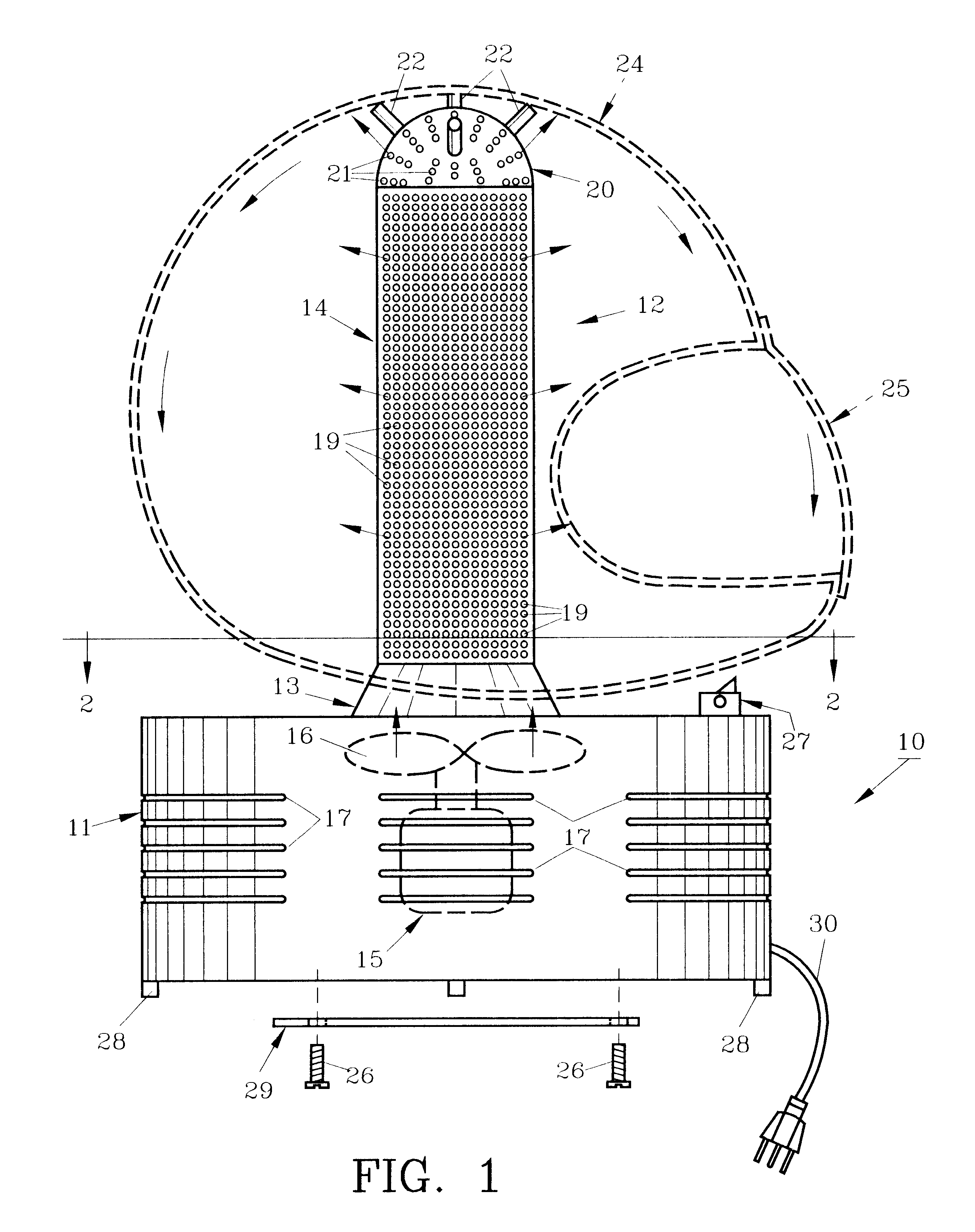
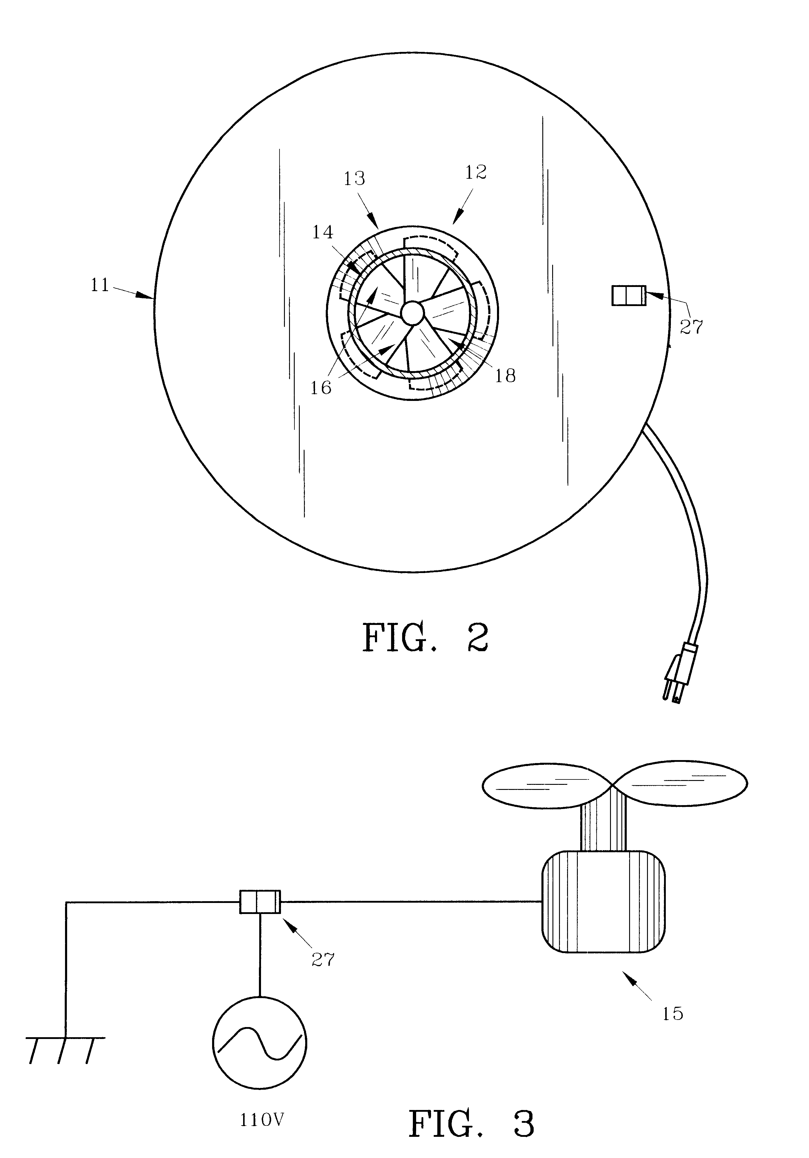
For a better understanding of the invention and its operation, turning now to the drawings, preferred helmet dryer 10 is shown in FIG. 1 having a base 11 which is cylindrically shaped (see also FIG. 2). Mounted atop base 11 is stanchion 12 which includes a relatively short inverted conical first section 13 joined to cylindrically shaped upper second section 14. Base 11, first section 13 and second section 14 are preferably formed from 0.080 inch aluminum sheeting and are fastened together preferably by rivets, although screws, weldments or the like can be used. Stanchion 13 is thus in fluid communication with base 11 via opening 18 (FIG. 2) and allows electric fan 15 having preferably five blades 16 to draw air through vents 17 and direct it upwardly through opening 18 in base 11, through stanchion first section 13, stanchion second section 14 and into dome 20. The directed air in second section 14 exits through apertures 19 therein to dry helmet 24. Directed air also is forced thro...


PUM


Abstract

The helmet dryer described includes an electric fan mounted in a base having a stanchion for supporting a helmet. The dryer provides convenience in removing moisture from a helmet worn during strenuous activities. The electric fan delivers air through perforations in the stanchion which circulates along the inside of the helmet for drying purposes. The helmet is separated from the stanchion by spacers affixed to a dome to insure a proper, complete air flow along the inside of the helmet.

Description

The invention herein pertains to drying articles which have been worn and particularly pertain to drying helmets used when racing vehicles such as automobiles.DESCRIPTION OF THE PRIOR ART AND OBJECTIVES OF THE INVENTIONPaper towels, hand-held blowers and other items have been used to wipe and dry the inside of helmets which are wet with perspiration after use by race car drivers. However, such "hand" drying removes only surface moisture and does not necessarily reach all the crevices and areas containing moisture along the inside of the helmet. Hence, when the driver uses the helmet again, such as for a second race on that day, he is confronted with a damp, uncomfortable helmet which can be distracting to his concentration.Thus, with the difficulties, inconvenience and incompleteness associated with drying the inside of a helmet by hand, whether using a towel or electric blower, the present invention was conceived and one of its objectives is to provide a simple, quick and effective...

Claims


Application Information

Patent Timeline
IPC IPC(8): F26B9/00
CPCF26B9/003A42B3/006
Inventor LEAMON, JR., J. WAYNE
Owner LEAMON JR J WAYNE
Learn More