
Bandwidth efficiency in cascaded scheme

a cascaded scheme and bandwidth efficiency technology, applied in the direction of data switching networks, digital transmission, electrical devices, etc., can solve the problems of reducing the effective bandwidth of the system, inefficient use of network switch modules' resources, and additional hops

Inactive Publication Date: 2003-04-08
ADVANCED MICRO DEVICES INC
View PDF9 Cites 51 Cited by
  • Summary
  • Abstract
  • Description
  • Claims
  • Application Information

AI Technical Summary

Problems solved by technology

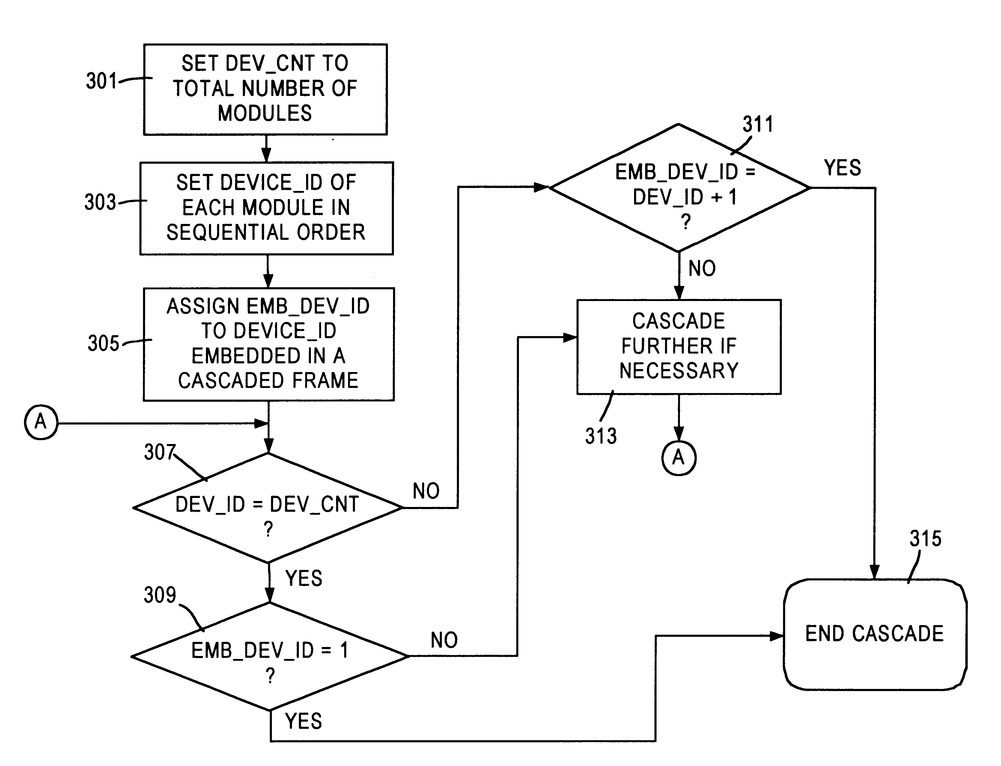
This results in inefficient use of the network switch modules' resources; in particular, the circulating frame reduces the effective bandwidth of the system in that resources consumed by this frame could have been utilized to forward other frames.
One major disadvantage with the above approach is that the frame is needlessly transferred back to the originating network switch module, resulting in an additional hop.
Moreover, the design complexity is significantly increased because the frame needs to be modified at each network switch module, thereby, requiring additional logic.
Thus, design complexity is not augmented.

Method used


Image

  • Bandwidth efficiency in cascaded scheme
  • Bandwidth efficiency in cascaded scheme
  • Bandwidth efficiency in cascaded scheme

Examples


Embodiment Construction

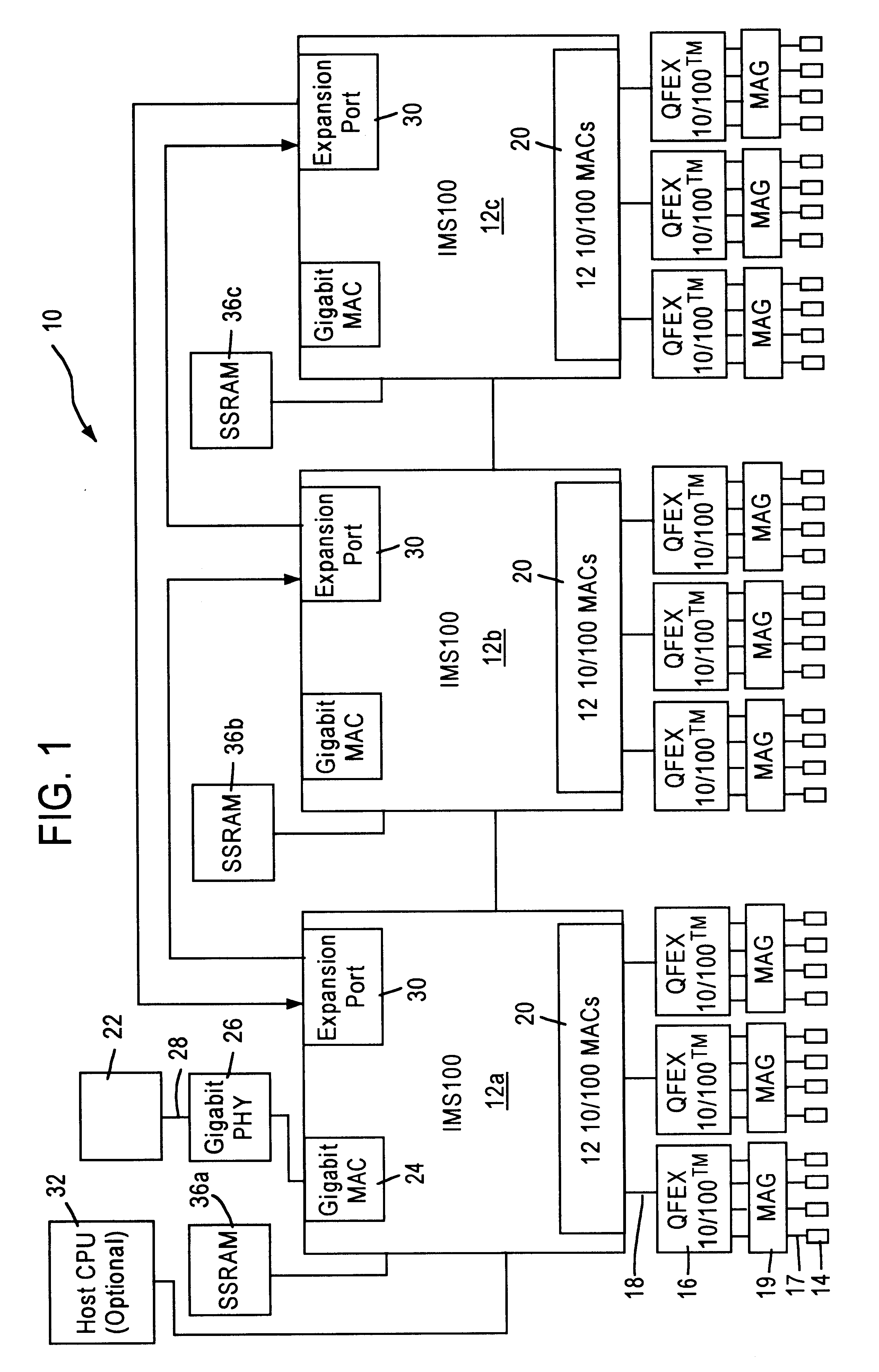
The present invention will be described with the example of a switch comprising three network switch modules. The switch operates in a packet switched network, such as an Ethernet (IEEE 802.3) network. It will become apparent, however, that the present invention is also applicable to other packet switched systems, as described in detail below, as well as to other types of systems in general.

Switch Architecture Overview

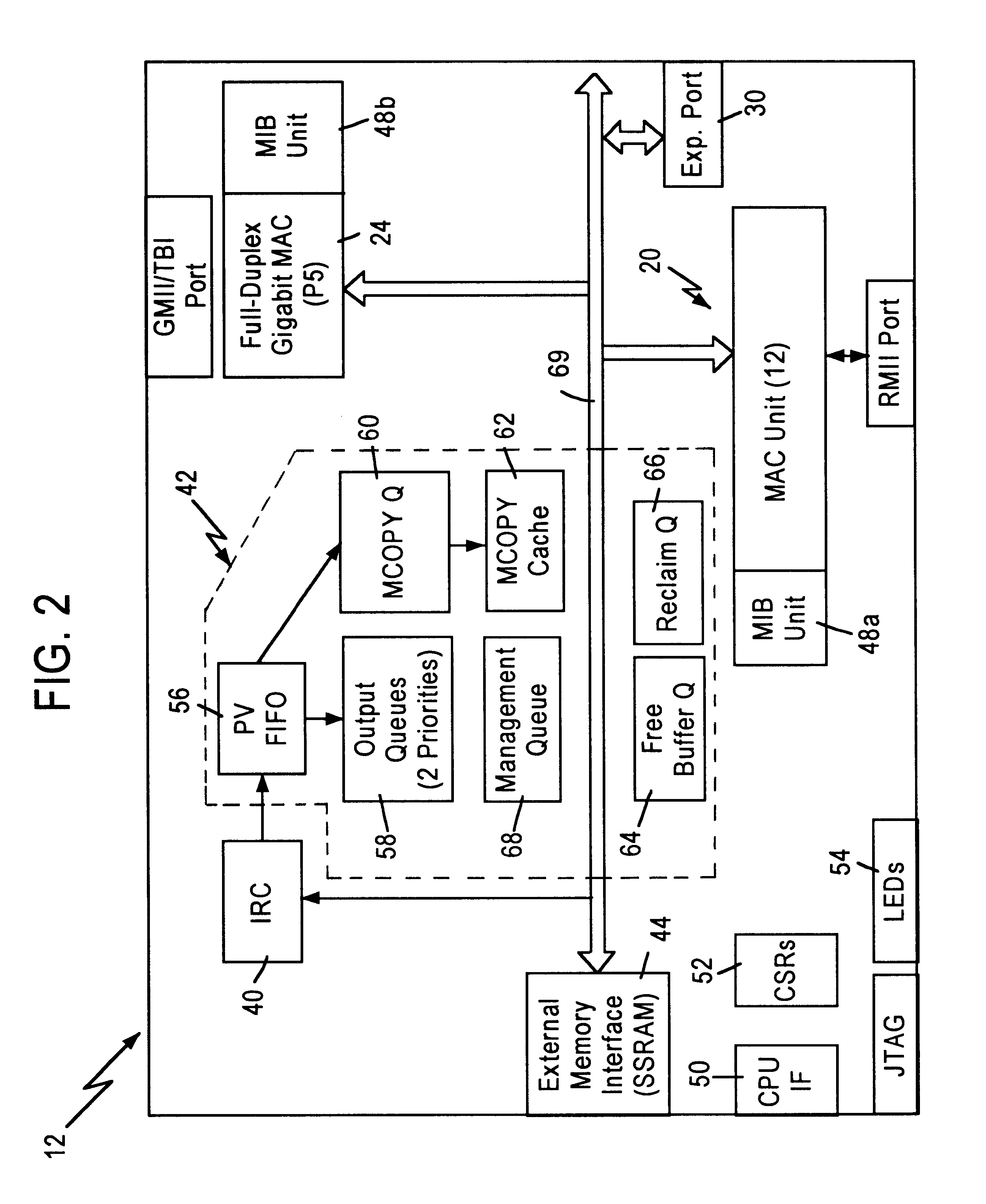
FIG. 1 is a block diagram of an exemplary system in which the present invention may be advantageously employed. The exemplary system 10 is a packet switched network, such as an Ethernet (IEEE 802.3) network. The packet switched network includes integrated multiport switch (IMS) 12 that enable communication of data packets between network stations. The term multiport switch and network switch module are used interchangeably. The network may include network stations having different configurations, for example twelve (12) 10 megabit per second (Mb / s) or 100 Mb / s network ...


PUM


Abstract

Network switch modules are cascaded in a prescribed sequence to support higher port requirements. The network switch modules may circulate a received frame indefinitely if the frame is not destined for any one of the output ports of the cascaded arrangement of network switch modules. Frame forwarding logic within each of the cascaded network switch modules is employed to determine when a network switch module should cease forwarding the received frame. Specifically, the frame forwarding logic takes the frame out of circulation based upon the sequence identifier of the network switch module and an embedded identifier associated with the frame.

Description

1. Technical FieldThe present invention relates to data communication networking devices, more particularly to an arrangement for forwarding frames in a cascaded scheme.2. Background ArtUsers of networking devices demand flexibility and scalability. To address this need, manufacturers have developed modular architectures that enable cascading of identical networking devices or network switch modules. By cascading these equipment (or components) in a loop, port density can be readily increased without redesign or development of costly interfaces.A cascaded arrangement is shown in FIG. 4, whereby three network switch modules 101, 103, and 105 are linked so that a received frame may be circulated to the proper output port. With all cascaded loop configurations, a received frame may circulate indefinitely if an appropriate output port cannot be determined among the ports of the three network switch modules 101, 103, and 105. This results in inefficient use of the network switch modules'...

Claims


Application Information

Patent Timeline
Patent Type & Authority Patents(United States)
IPC IPC(8): H04L12/56
CPCH04L49/15H04L49/1553H04L49/253H04L49/351H04L49/354H04L49/20H04L49/30H04L49/45H04L49/3054H04L49/352H04L49/3009
Inventor MERCHANT, SHASHANK C.YU, CHINGWILLIAMS, ROBERT ALAN
Owner ADVANCED MICRO DEVICES INC
Learn More