Card lock

Inactive Publication Date: 2003-03-04
ASSA
View PDF6 Cites 10 Cited by
  • Summary
  • Abstract
  • Description
  • Claims
  • Application Information

AI Technical Summary

Benefits of technology

The object of the present invention is to provide a card lock wherein the card is protected against damage.

Problems solved by technology

The disclosed device is not suitable for operating an extendable / retractable bolt.

Method used


Image

  • Card lock
  • Card lock
  • Card lock

Examples


Embodiment Construction

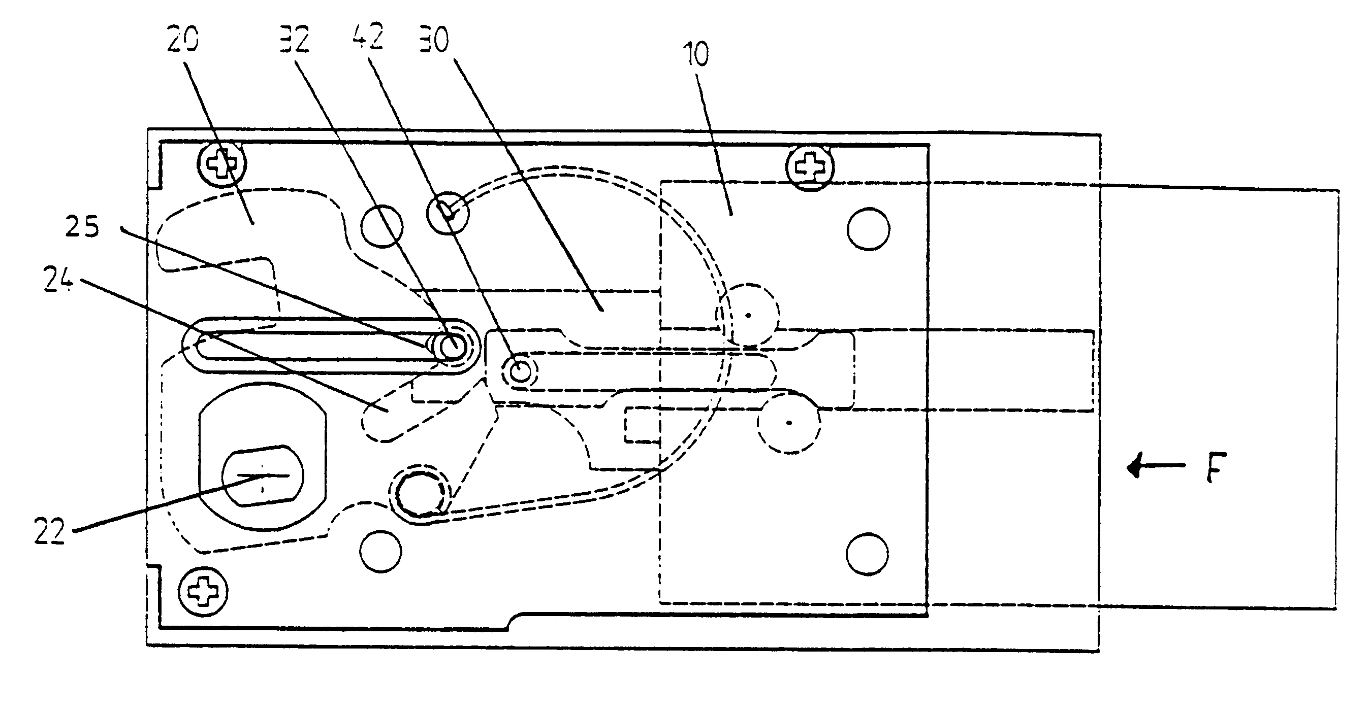
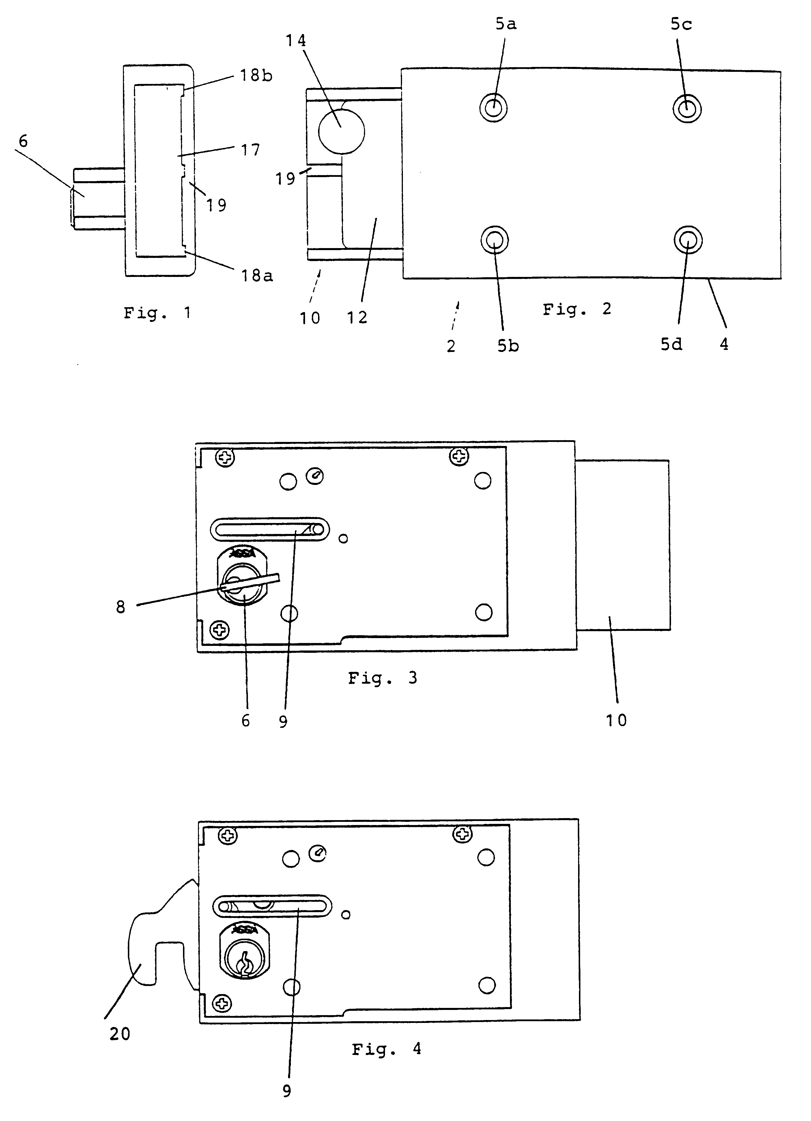
FIGS. 1-4 illustrate schematically the main parts of an embodiment of a card lock according to the invention. The card lock, generally designated by the numeral 2, consists of a housing or casing 4 and a cassette 10 for insertion of a card, not shown, of a conventional size for cash cards, into a card space or compartment 12 in order to activate the locking device. The locking device also comprises a pivotal catch hook 20 and a cylinder lock 6, the key 8 of which can be removed when a proper card has been inserted into the cassette 10 and the catch hook has been extended to the lock position shown in FIG. 4 by means of a key. The dogging elements, not shown, of the cylinder plug effect in a normal way the swinging movements of the catch hook.

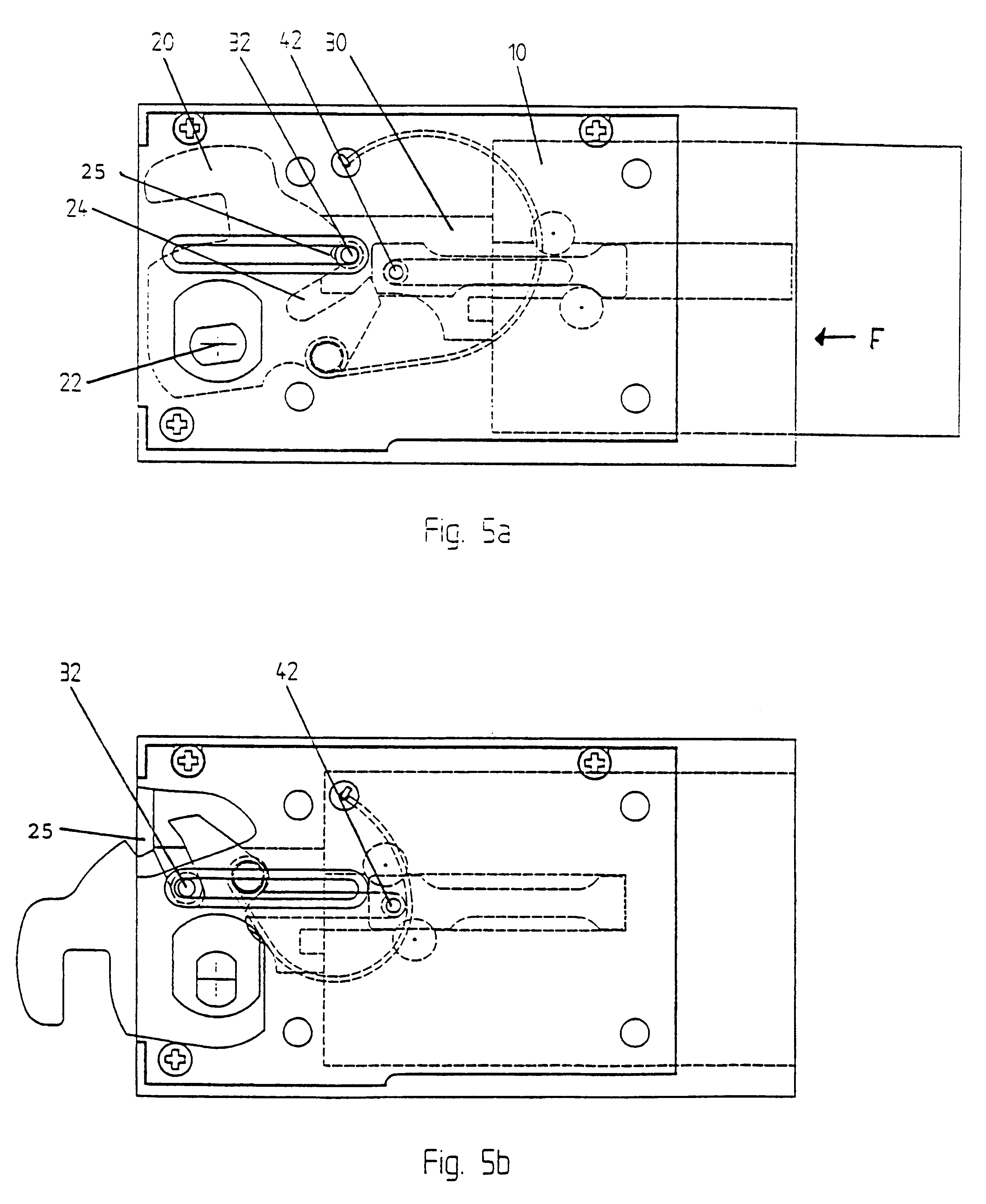
An intermediate member 30, see FIGS. 5a and 5b, is connected to the catch hook 20 through a pin 32 running in a slot 24 in the catch hook so that the swinging movements of the catch hook in different directions about the point 22 are translated ...


PUM


Abstract

A locking device comprises a housing (4), a bolt means mounted in the housing and an intermediate member connected to the bolt means and adapted for an essentially rectilinear movement back and forth between a first end position, in which the bolt means is retracted, and a second end position, in which the bolt means is extended. The locking device also comprises a latch means restricting the movement of the intermediate member when a proper code card has not activated the locking device. A cassette (10) , which is integrated with the intermediate member and has a card space (12) for reception of the card in a position that activates the locking device, is provided with a frame (17), which fully hides the card from the outside when the bolt means is extended.

Description

The present invention relates to a card lock, and more particularly to a card lock wherein a cassette is used for receiving a code card activating the locking function.Card locks are previously known and are often installed in e.g. indoor swimming baths and other sport establishments where a new person uses the lock several times during the same day. A card is then handed over which enables locking of a certain storage locker or the like and this card should for the most part be returned after usage.The U.S. patent publication U.S. Pat. No. 4,918,957 (Eisermann) discloses a lock with a locking function that is released by insertion of a coded card. The object of the lock according to Eisermann is to prevent repeated locking with the card still in the lock, because then the card can remain in the door when the lock is brought to a locked position with the door open.The European patent publication 0 066 558 A2 discloses a card controlling device with a movable drawer member provided w...

Claims


Application Information

Patent Timeline
IPC IPC(8): G07F7/08
CPCG07F7/0833G07F7/08Y10T70/7531Y10T70/7757
Inventor HAGGSTROM, .ANG.KE
Owner ASSA
Why Eureka
Try Eureka