
Radio selective calling receiver and portable telephone apparatus for efficiently managing received call

a mobile telephone and receiver technology, applied in the field of radio selective calling receivers, can solve the problems of difficult management of new registration, change, delete, and check the notification, and difficulty in assigning notification means and valid time to the sending user

Inactive Publication Date: 2002-06-25
NEC CORP
View PDF19 Cites 46 Cited by
  • Summary
  • Abstract
  • Description
  • Claims
  • Application Information

AI Technical Summary

Benefits of technology

The radio selective calling receiver further comprising a means for setting up and storing a plurality of sending users for the sending user information. The radio selecting calling receiver further comprising a first searching and controlling means for preventing a plurality of sending users for the sending user information and the sending user information from being redundantly registered, and a second searching and controlling means for preventing the time information corresponding to the sending user information from being inconsistent with the current time and date.

Problems solved by technology

However, when there are a large number of sending users, it is troublesome to assign notifying means and valid time to the sending users.
In other words, it is difficult to manage (newly register, change, delete, and check) notifying means and notification valid time ranges for these sending users.

Method used


Image

  • Radio selective calling receiver and portable telephone apparatus for efficiently managing received call
  • Radio selective calling receiver and portable telephone apparatus for efficiently managing received call
  • Radio selective calling receiver and portable telephone apparatus for efficiently managing received call

Examples


first embodiment

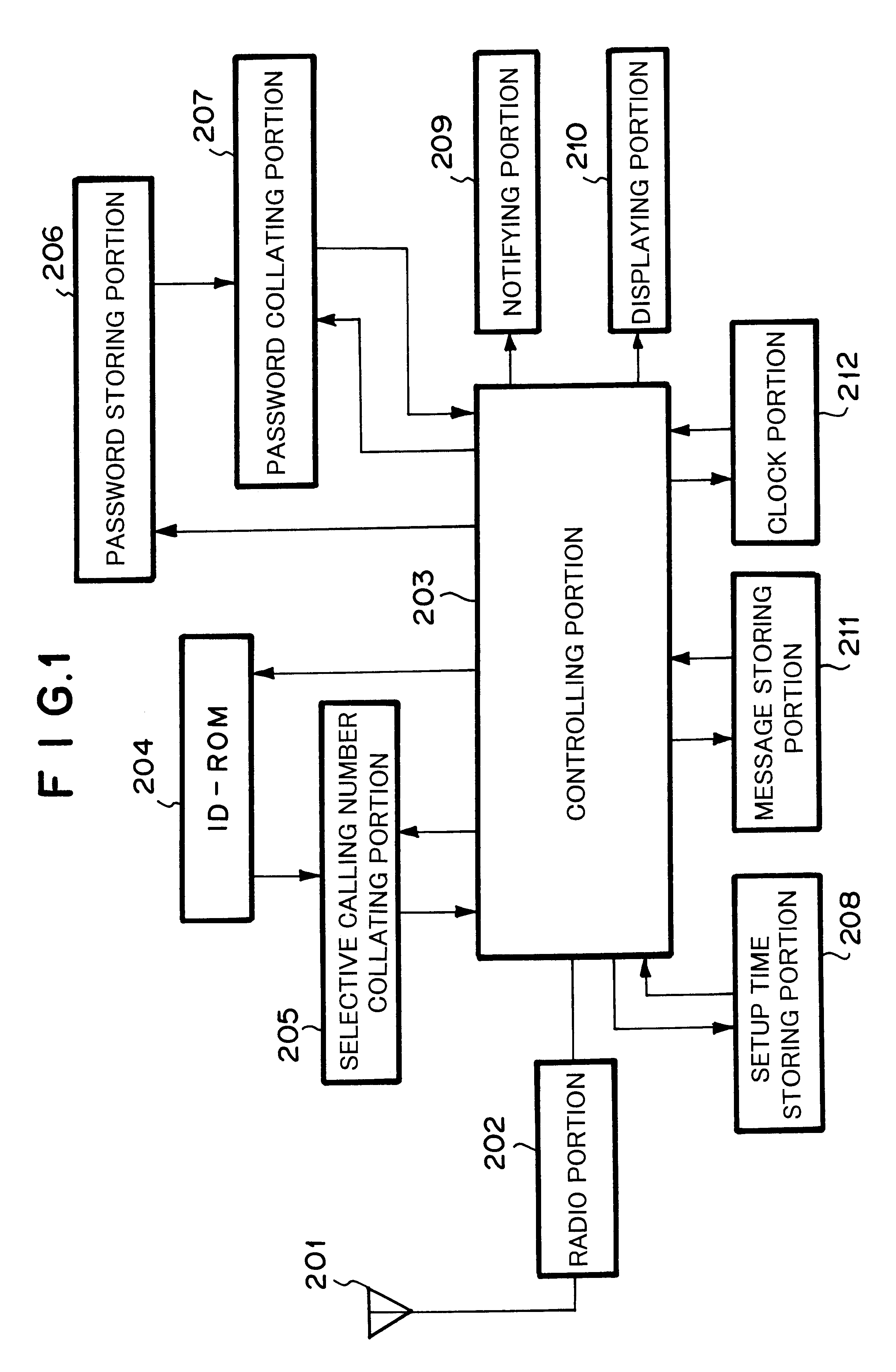
FIGS. 2A and 2B are block diagrams showing examples of the structures of receivers according to a first embodiment of the present invention. In FIG. 2A, a radio selective calling receiver (hereinafter referred to as receiver) according to the first embodiment comprises a radio portion 1, a main controlling portion 2, an ID-ROM portion 3, a message storing portion 6, a data inputting portion 7, a sending user calling information storing portion 10, a sub-controlling portion 9, a clock-calendar portion 8, a reception notifying portion 4, and a displaying portion 5. The radio portion 1 receives and demodulates a radio calling signal.

The main controlling portion 2 processes a received signal and controls a receiving operation and so forth. The ID-ROM portion 3 stores a local calling number and so forth. The message storing portion 6 stores a received message and so forth. The data inputting portion 7 inputs sending user information and so forth. The sending user calling information stor...

second embodiment

Next, a second embodiment of the present invention will be described.

FIG. 11 is a block diagram showing the structure of a receiver according to the second embodiment of the present invention. The receiver shown in FIG. 11 comprises a radio portion 1, a main controlling portion 2, an ID-ROM portion 3, a message storing portion 6, a data inputting portion 7, a clock-calendar portion 8, a reception notifying portion 4, and a displaying portion 5 that have the same functions and operations as those of the receiver shown in FIGS. 2A and 2B. For simplicity, their description will be omitted. In the first embodiment, sending user information should be managed in detail. On the other hand, in the second embodiment, in addition to the above-described sub-controlling portion 9 and the sending user calling information storing portion 10, a sending user storing portion 11 is disposed. The sending user storing portion 11 stores the relation between sending users and sending user information.

FIG...


PUM


Abstract

A radio selective calling receiver comprising a receiving for receiving the radio calling signal containing sending user information that allows the receiving user to identify the sending user and assign a priority level to the sending user, a plurality of types of notifying for notifying the receiving user of the received radio calling signal in different manners, a time counting for setting up and counting the current time and date, an information storing for setting up and storing notification state information and time information through information inputting and information displaying for the receiving user, the notification state information representing a receiving operation and a notifying operation of the radio calling signal, the time information representing a valid date range and a valid time range of the receiving operation and the notifying operation, and a controlling for searching, collating, searching, comparing and controlling the notifying operations corresponding to the searched notification state information.

Description

1. Field of the InventionThe present invention relates to a radio selective calling receiver, in particular, to a controlling means that the user of the receiver sets up a receiving operation and a reception notifying operation for each sending user. The present invention also relates to a setup controlling means that is disposed in a TDMA type or CDMA type portable telephone unit.2. Description of the Related ArtA conventional radio selective calling receiver (a well-known pager, an IS-136, an IS-95, FLEX, FLEX-TD, a pocket-bell, a PDC(Personal Digital Cellular) and so forth) (hereinafter referred to as receiver) has a plurality of notifying means such as a sounding means (for example, a speaker), a vibrating means (for example, a motor), and a lighting means (for example, an LED). One notifying means is used for all received signals. Alternatively, a plurality of calling numbers are assigned respective notifying means.In recent years, a receiver with a password-protected reception...

Claims


Application Information

Patent Timeline
Patent Type & Authority Patents(United States)
IPC IPC(8): G08B5/22G08B3/00G08B3/10H04B1/40H04M1/66H04Q7/14H04M1/663H04M1/57H04M1/725H04M1/72H04M1/72451H04W88/02
CPCG08B3/1041G08B5/227H04B1/401H04W88/022H04M1/663H04M1/72566H04M1/57H04M1/72451
Inventor MINATA, SHIGEKI
Owner NEC CORP
Learn More