
Control panel with a printed circuit, in particular for a motor vehicle

a technology of printed circuits and control panels, which is applied in the direction of instrument arrangements, ticket-issuers, support structure mounting, etc., can solve the problems of inability to conveniently accommodate electronic components and connecting tracks, too little space available, and high cost of arrangements, so as to avoid any gap or clearance, improve sealing against dust ingress, and facilitate adjustment

Inactive Publication Date: 2001-10-09
VALEO ELECTRONIQUE SA
View PDF10 Cites 4 Cited by
  • Summary
  • Abstract
  • Description
  • Claims
  • Application Information

AI Technical Summary

Benefits of technology

Because of the above mentioned retaining means, the position of the computer circuit board can be easily adjusted in such a way that the display device will be in a position which is defined with respect to the front panel, that is to say generally in direct or indirect engagement with, and behind, a rear face of the front panel. As a result, the display device is held firmly flat against the back of the front panel, avoiding any gap or clearance, and this improves sealing against the ingress of dust, besides improving the general appearance. In addition, it eliminates any risk of noise due to vibration, and enables the effect of manufacturing tolerances to be ignored. A further advantage of this arrangement is that it reduces the connections between the display device and the computer circuit board, and gives improved protection against electrical discharges, by separating the connecting system from the front panel.

Problems solved by technology

This arrangement has the disadvantage that it leaves too little space available to accommodate conveniently the electronic components and the connecting tracks associated with the printed circuit.
All of these arrangements are costly and do not always enable correct retention of the display device in engagement behind the front panel to be guaranteed.
As a result of this, vibrations can be set up, and a gap may appear at the perimeter of the display device.

Method used


Image

  • Control panel with a printed circuit, in particular for a motor vehicle
  • Control panel with a printed circuit, in particular for a motor vehicle
  • Control panel with a printed circuit, in particular for a motor vehicle

Examples


Embodiment Construction

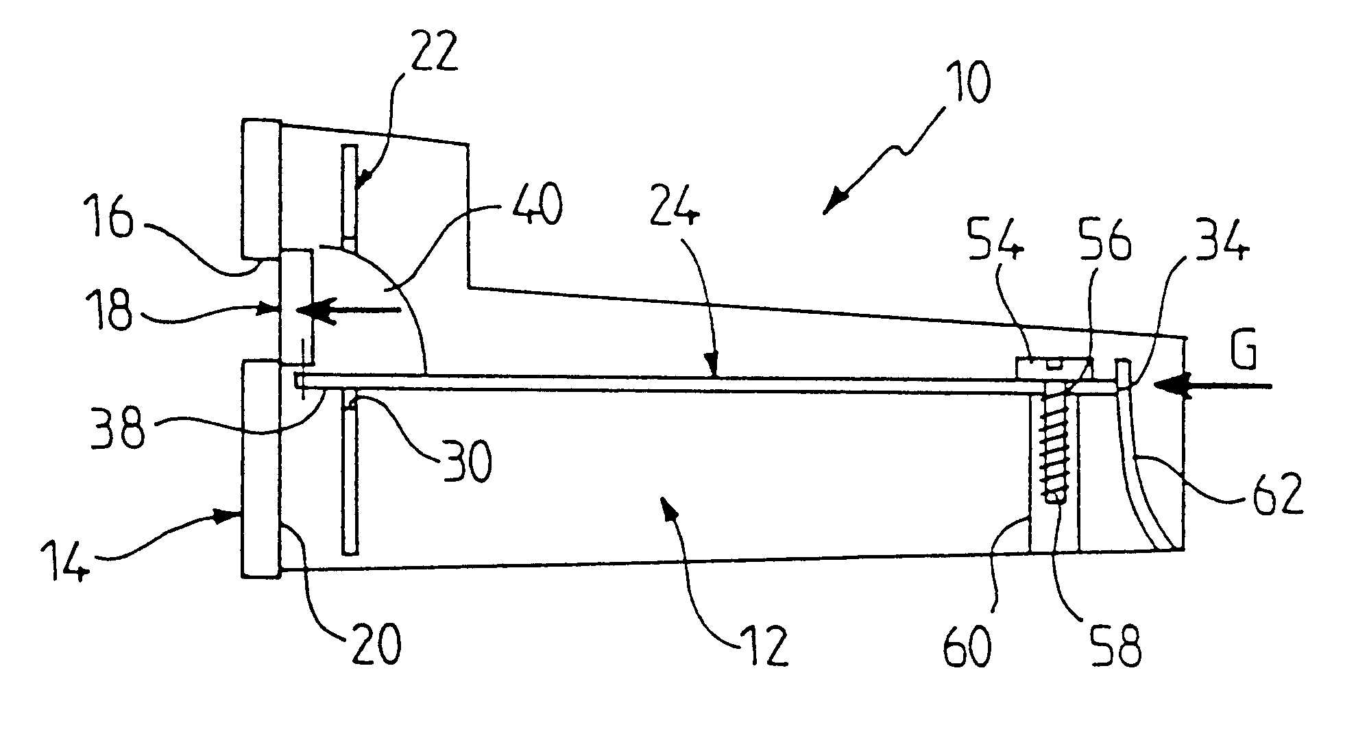
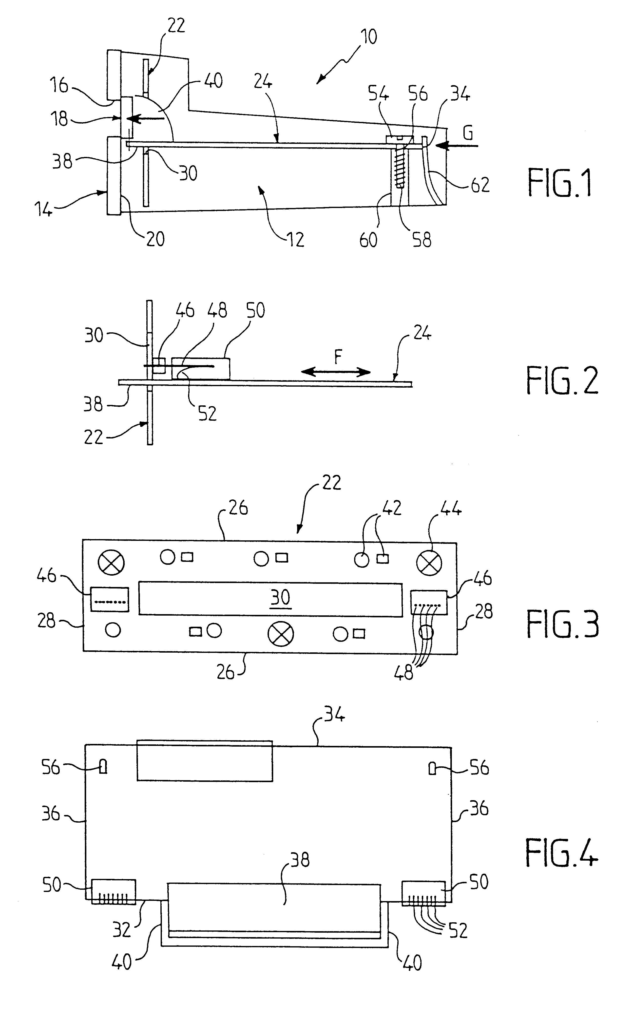
Reference is first made to FIG. 1 which shows a control unit or panel 10, which in this example is arranged to control an installation for heating and air conditioning the cabin of a motor vehicle. The control panel 10 includes a body 12 made in the form of a casing which is moulded in a suitable plastics material. The body 12 includes a front panel, or face panel, 14 which is arranged to be incorporated, in a substantially vertical position, into the fascia or console of the vehicle.

The front panel 14 is formed with a window 16 of generally rectangular form, behind which a display device 18 of the liquid crystal type is placed. In this example, the display device 18 is substantially rectangular and its dimensions are generally greater than those of the window 16, so that it abuts against a rear face 20 of the front panel 14. In another version, the display device may consist of a simple through hole or several through holes, the display device itself consisting of one or more eleme...


PUM


Abstract

A control panel or control unit for a motor vehicle heating and air conditioning circuit comprises a body having a front panel, and contains a printed circuit which comprises a front circuit board located behind the front panel and having an aperture, together with a computer circuit board which makes an angle with the front circuit board. The computer circuit board has an extension portion which passes through the aperture in the front circuit board, and this extension portion carries a display device which is located behind an aperture formed through the front panel. Retaining means, for example adjustable fastening means, are interposed between the computer circuit board and the body so as to secure the display device in a defined position with respect to the front panel.

Description

This invention relates to control units, also referred to as control panels, of the type having a printed circuit which is intended most particularly for use in a motor vehicle, especially for the purpose of being actuated by an occupant of the vehicle in order to control some function of the vehicle.Control panels of this type are already known which comprise a body having a front panel, a printed circuit carried by the front panel, and a display device which is connected to the printed circuit and which is located behind a window formed through the front panel. Such a panel may for example be used for controlling an installation for heating and / or air conditioning the cabin of a motor vehicle.The front panel of the control panel (or control unit) is conventionally incorporated in a substantially vertical position within the fascia or console of the motor vehicle, so that the display device can be visible to the driver. Conventionally again, the front panel contains a keypad consis...

Claims


Application Information

Patent Timeline
Patent Type & Authority Patents(United States)
IPC IPC(8): B60R16/02B60K37/02
CPCB60K37/02B60R16/02B60K2350/302B60K2350/307B60K2350/946B60K35/60B60K2360/42B60K2360/46B60K35/50
Inventor LACROIX, LOUISTOUSSAINT, ALAIN
Owner VALEO ELECTRONIQUE SA
Learn More