Eureka AIR delivers breakthrough ideas for toughest innovation challenges, trusted by R&D personnel around the world.

Container with self-heating module having liquid reactant and breakable reactant barrier at distal end of module

a self-heating module and container technology, applied in the field of containers, can solve the problems of difficulty in judging the time period specified in the container instructions, and the contents of the container are consumed

Inactive Publication Date: 2001-01-30
ONTRO
View PDF18 Cites 92 Cited by
  • Summary
  • Abstract
  • Description
  • Claims
  • Application Information

AI Technical Summary

Benefits of technology

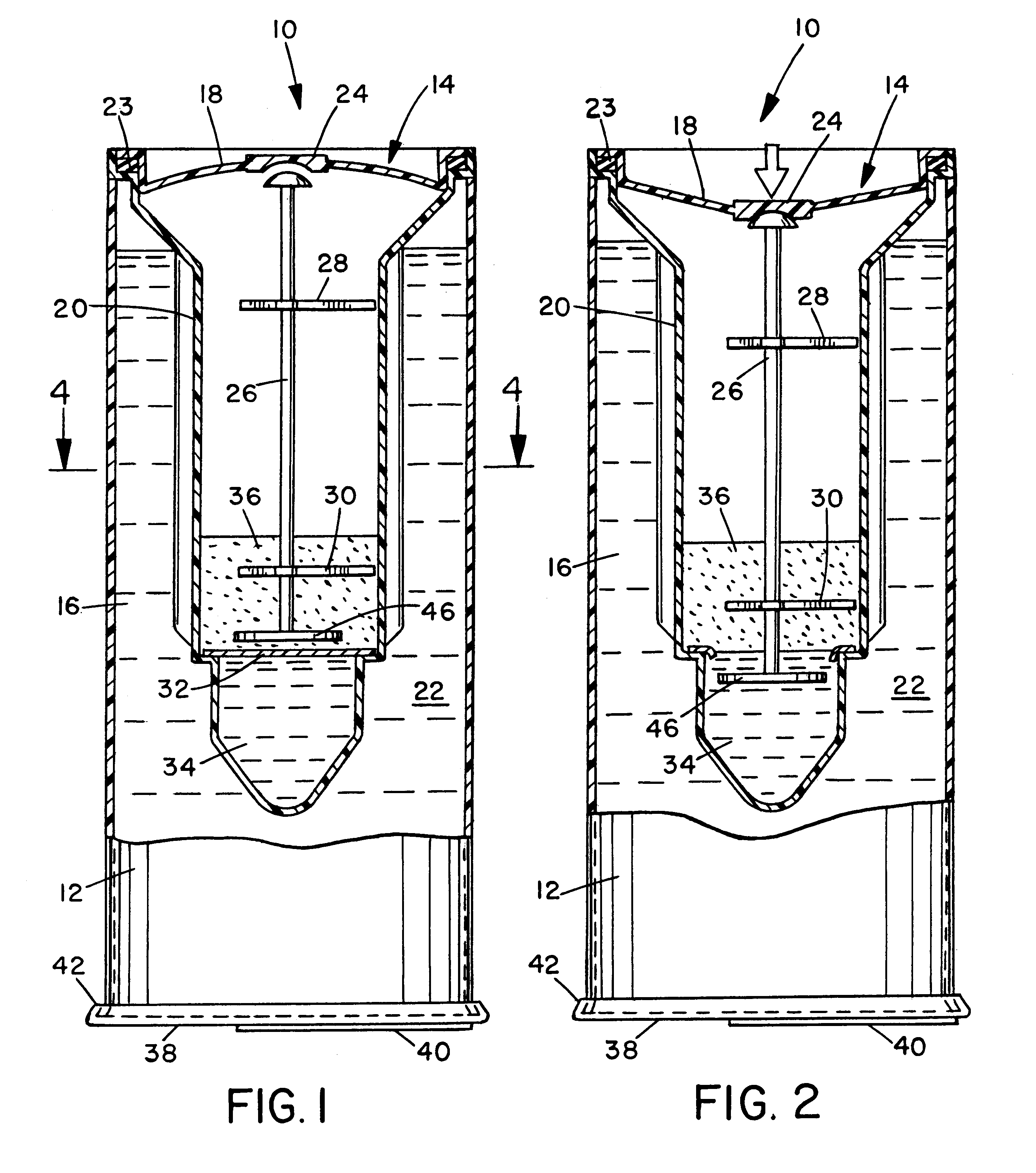
When a user actuates the thermic module, an elongated actuator member coaxially oriented in the elongated reaction chamber moves in an axial direction and punctures the barrier. The user can then immediately invert the container, allowing the liquid reactant to drain through the puncture into the solid reactant in the reaction chamber. The reactants mix and produce a reaction that, depending upon the reactants, either produces heat, i.e., an exothermic reaction, and thereby heats the container contents, or uses heat, i.e., an endothermic reaction, and thereby cools the container contents. An advantage of the present invention is that the user does not need to wait to invert the container after actuating it. Rather, the user can actuate the container, immediately invert it, wait until the contents reach the desired temperature, and consume the contents through the closure.

Problems solved by technology

The user inverts the container and, when the contents have reached the desired temperature, consumes the contents.
A potential problem is that most persons have difficulty judging the period of time specified in the container instructions.
Also, typical users of self-heating beverage containers are those who may be out of doors, on the go, or otherwise do not have convenient and immediate access to a timepiece.

Method used


Image

  • Container with self-heating module having liquid reactant and breakable reactant barrier at distal end of module
  • Container with self-heating module having liquid reactant and breakable reactant barrier at distal end of module
  • Container with self-heating module having liquid reactant and breakable reactant barrier at distal end of module

Examples


Embodiment Construction

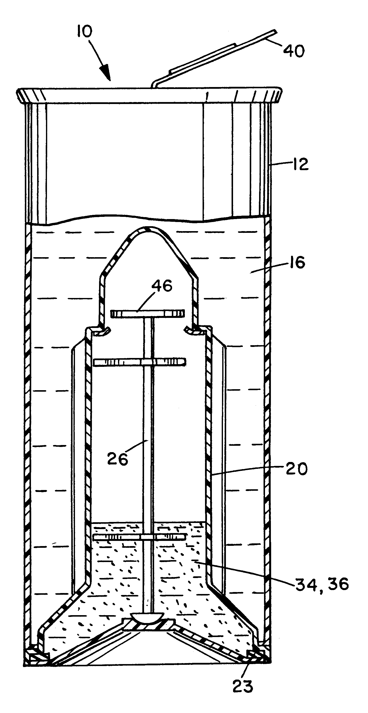
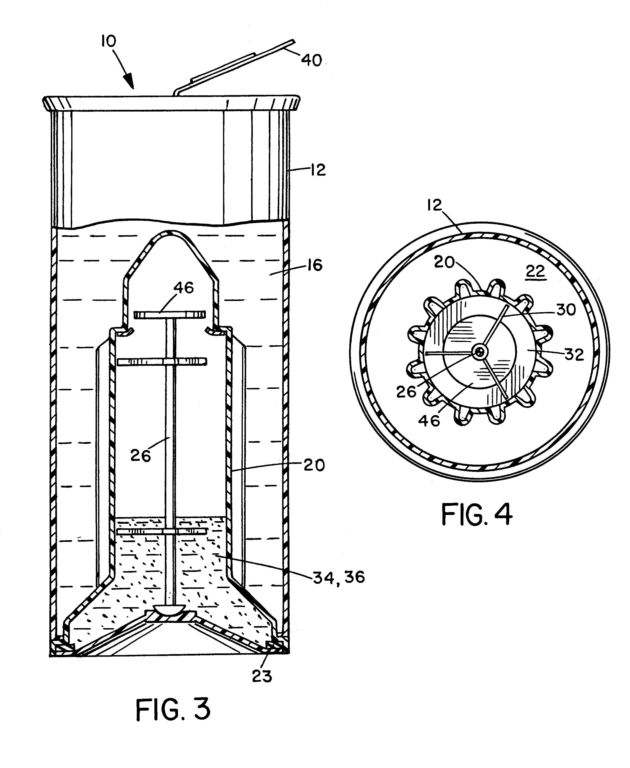
A container 10 includes a container body 12 and a thermic module 14 that transfers heat between it and the contents 16 of container 10. Although any of a variety of manufacturing methods and materials may be suitable, container body 12 is preferably made of blow-molded food-grade plastic. Thermic module 14 includes a thermic module cap 18 and a thermic module body 20. Module body 20 is joined to container body 12 by a suitable plastic welding process. Nevertheless, in other embodiments module body 20 may alternatively be formed unitarily with container body 12 as portions of a unitary molded body. The elongated portion of module body 20 that functions as a heat-exchanger is preferably fluted or pleated to promote heat transfer. (See FIG. 4.) Contents 16, which may be a beverage, food, medicine or any other suitable material, are contained in a material chamber 22.

Module cap 18 is press-fit in the proximal end of module body 20. A gasket or filter ring 23 is disposed between the adjo...


PUM

PropertyMeasurementUnit
timeaaaaaaaaaa
time periodaaaaaaaaaa
temperatureaaaaaaaaaa

Abstract

A self-heating or self-cooling container has a container body, a closure at one end of the body through which the contents of the container can be consumed, and a thermic module at the other end of the body having an actuator portion and an elongated reaction chamber portion that extends distally into the container body and contains a liquid reactant relatively more distally from the actuator portion than a solid reactant separated from the liquid reactant by a breakable barrier. When a user actuates the thermic module, an elongated actuator member punctures the barrier. The user can then immediately invert the container, allowing the liquid reactant to drain through the puncture into the solid reactant in the reaction chamber. The reactants mix and produce a reaction that, depending upon the reactants, either heats or cools the container contents by conduction through the thermic module wall. An advantage is that the user does not need to wait to invert the container after actuating it. Rather, the user can actuate the container, immediately invert it, wait until the contents reach the desired temperature, and consume the contents through the closure.

Description

1. Field of the InventionThe present invention relates generally to containers that include an internal chemical-based module that heats or, alternatively, cools the material, such as a food, beverage, medicine, or the like, in the surrounding container.2. Description of the Related ArtContainers may have integral modules for warming materials in the container, such as Japanese sake, coffee, or soup. Examples of such self-heating containers are disclosed in U.S. Pat. Nos. 5,461,867 and 5,626,022, issued to Scudder et al. Such containers typically include an outer can or body, in which the food or beverage is sealed, and an inner can orthermic module that contains two chemical reactants that are stable when separated from one another but, when they mix in response to actuation of the thermic module by a user, produce an exothermic reaction or, alternatively, an endothermic reaction and thereby heat or cool the contents of the container.The heating or cooling module (thermic module) i...

Claims


Application Information

Patent Timeline
Patent Type & Authority Patents(United States)
IPC IPC(8): A47J36/28A47J36/24B65D81/34C09K5/00C09K5/18F25D5/02F25D5/00
CPCA47J36/28B65D81/3484C09K5/18F25D5/02F25D2331/804
Inventor SCUDDER, JAMES A.BERNTSEN, JAMES L.
Owner ONTRO
Why Eureka
Eureka Blog
Learn More