Socket with Engaging Structure
a technology of socket and socket body, applied in the field of sockets, can solve the problems of reducing the friction between the socket and the tool member, and the difficulty of bringing the tool member into engagemen
- Summary
- Abstract
- Description
- Claims
- Application Information
AI Technical Summary
Benefits of technology
Problems solved by technology
Method used
Image


Examples
first embodiment
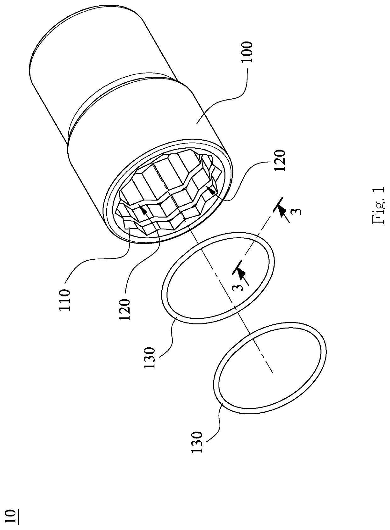
[0028]More specifically, the at least one stop ring 130 may be a closed stop ring or an open stop ring; the present disclosure has no limitation in this regard. In the first embodiment, each stop ring 130 is a closed stop ring to simplify the manufacturing process of the stop ring 130.
[0029]The at least one stop ring 130 may be made of an elastic material or metal. The present disclosure has no limitation on the material of the at least one stop ring 130. In the first embodiment, each stop ring 130 is made of an elastic material to increase the elasticity with which the stop ring 130 can engage with the tool member.
[0030]In the first embodiment, the number of the at least one groove 120 and the number of the at least one stop ring 130 are both two. The present disclosure, however, has no limitation on the aforesaid numbers. In other words, the numbers and arrangements of the at least one groove 120 and of the at least one stop ring 130 may be adjusted according to the specifications...
third embodiment
[0035]More specifically, the stop ring 330 may be made of an elastic material or metal. The present disclosure has no limitation on the material of the stop ring 330. In the third embodiment, the stop ring 330 is made of metal in order to have high wear resistance.
[0036]Moreover, the stop ring 330 may be a closed stop ring or an open stop ring; the present disclosure has no limitation in this regard. In the third embodiment, the stop ring 330 is an open stop ring. More specifically, the stop ring 330 has two ends 330a and 330b. The stop ring 330 surrounds the central axis of the socket body (not shown in FIG. 5) in such a way that the two ends 330a and 330b define a reflex central angle θ satisfying the condition: 270°≤θ≤360°. This configuration helps increase the smoothness of disposing the stop ring 330 in the corresponding groove.
[0037]Please refer to FIG. 6 for a sectional view of a stop ring 430 of the socket with an engaging structure according to the fourth embodiment of the ...
fourth embodiment
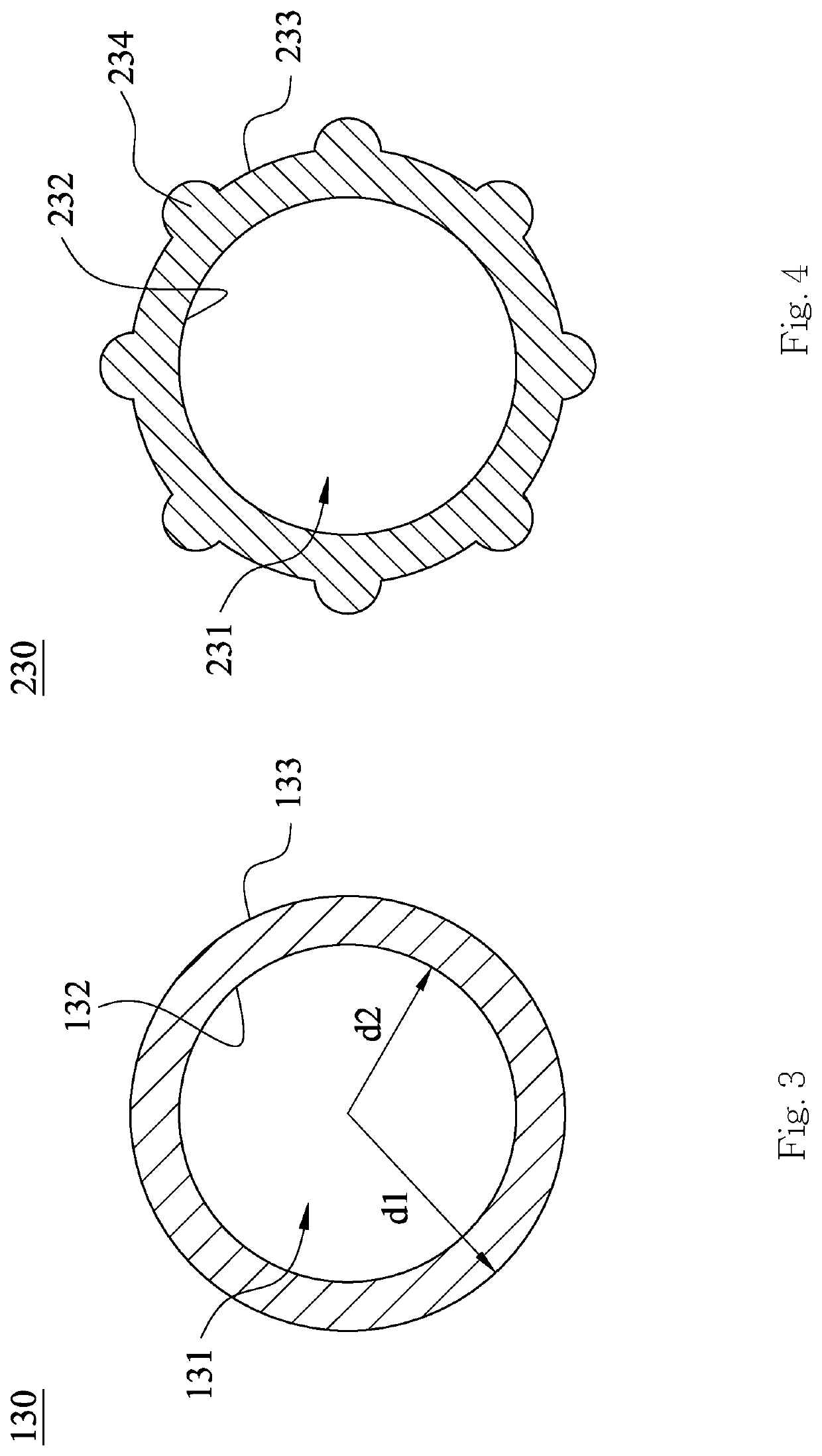
[0038]As shown in FIG. 6, the stop ring 430 has a polygonal cross section; the present disclosure, however, has no limitation on the cross-sectional shape of the stop ring. It is worth mentioning that the cross-sectional shape of the hollow cavity 431 is different from that of the stop ring 430. In the fourth embodiment, the stop ring 430 has a rectangular cross section whereas the hollow cavity 431 has a circular cross section; the present disclosure, however, has no limitation on the shapes of those cross sections. The present disclosure allows stop rings of different shapes to be provided to meet the requirements of different tool members.
[0039]As in the first embodiment, in which there are two stop rings 130, the fourth embodiment includes two stop rings 430. The at least one hollow cavity 431 and the at least one inner surface 432 of each stop ring 430 are the same as the at least one hollow cavity 131 and the at least one inner surface 132 of each stop ring 130 in the first em...
PUM
 Abstract
Description
Claims
Application Information
 - R&D
- Intellectual Property
- Life Sciences
- Materials
- Tech Scout
- Unparalleled Data Quality
- Higher Quality Content
- 60% Fewer Hallucinations
Browse by: Latest US Patents, China's latest patents, Technical Efficacy Thesaurus, Application Domain, Technology Topic, Popular Technical Reports.
© 2025 PatSnap. All rights reserved.Legal|Privacy policy|Modern Slavery Act Transparency Statement|Sitemap|About US| Contact US: help@patsnap.com