Syringe plunger finger ring structures

a technology of plunger finger and syringe, which is applied in the field of syringes, can solve the problems of difficult operation, difficult control of syringe content, and limited plunger ring surface of syringe, and achieves the effects of convenient plunger operation, selectively reducing open area, and more controllable operation

Active Publication Date: 2022-05-12
ALGER & KLEMER
View PDF2 Cites 0 Cited by
  • Summary
  • Abstract
  • Description
  • Claims
  • Application Information

AI Technical Summary

Benefits of technology

[0004]Disclosed is an ergonomically improved conventional and dental syringe including adjustable ring structure that substantially surround the operator finger with portions of the syringe member that receives an operator finger, which facilitates convenient plunger operation and more controllably to accomplish both the distal (injecting) stroke and the proximal (aspirating) stroke.
[0005]In various embodiments, the present invention provides or connects to a syringe that comprises a syringe body capable of having a volume of material therein and a plunger disposed to enter the syringe body and dispense material from the syringe body by movement of plunger, and a novel a finger ring and related structures having an open area and connected to the plunger adapted to receive a finger within the finger ring open area, including a spacer of various embodiments inserted within the open area to selectively reduce the open area and provide more controllable engagement of the syringe plunger by the operator finger.
[0006]Those embodiments make the syringe significantly more easy, predictable, and controllable to use with both the distal (injecting) stroke and the proximal (aspirating) stroke. The result is a syringe and syringe attachment(s) which enables a reliable and controlled aspiration maneuver and to perform delicate but routine actions, e.g. to test for the presence of blood indicating that a blood vessel has been penetrated, and other critical operations, easily and controllably with one hand.

Problems solved by technology

Existing conventional and dental syringes typically have limited plunger ring surfaces.
This drawback makes it hard to operate and hard to control the dispensing of syringe content.

Method used


Image

  • Syringe plunger finger ring structures
  • Syringe plunger finger ring structures
  • Syringe plunger finger ring structures

Examples


Embodiment Construction

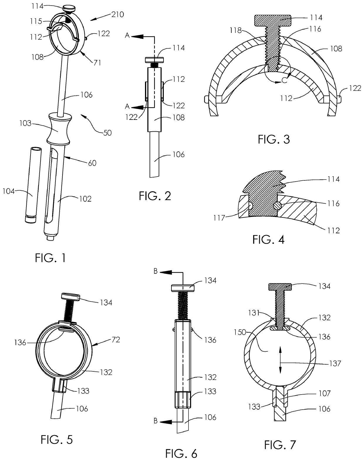
[0044]A first embodiment 71 according to the present invention is shown in FIGS. 1-4, wherein the syringe 50 of the perspective and side elevation views FIGS. 1 and 2, and cross-sectional and enlarged cross-sectional views of FIGS. 3 and 4, includes a syringe body 102, that typically includes a narrowed or other shaped region 103 for grasping or retention between fingers, receives or includes a cartridge 104 with medication, etc., a piston (not shown) or plunger that compresses a portion of the inserted syringe cartridge 104 by downward movement of a plunger shaft 106 to dispense the medication, and further includes a first ring embodiment 71 on the operating (finger) end of the syringe plunger 106, sized and shaped to accommodate a large finger. The ring embodiment 71 enables the plunger 106 to receive finger compression and withdrawal forces, and includes a movable segment 112 that is adjustable to more closely fit around inserted fingers (‘finger’ herein includes thumbs) of varyi...


PUM


Abstract

A syringe finger ring and finger ring inserts, that in various embodiments, provides or connects to a syringe that comprises a syringe body capable of having a volume of material therein and a plunger disposed to enter the syringe body and dispense material from the syringe body by movement of plunger, and a novel a finger ring and related structures having an open area and connected, by various structures, to the plunger adapted to receive a finger within the finger ring open area, including a spacer of various embodiments inserted within the open area to selectively reduce the open area and provide more controllable engagement of the syringe plunger by the operator finger in distal and proximal strokes.

Description

[0001]Priority is claimed on Provisional Patent Application No. 63 / 071,409 filed 28 Aug. 2020, entitled Adjustable Ring Structure For Dental Syringe.Field of the Invention[0002]The present invention relates to syringes in particular, to conventional and dental syringes having finger receptacle to better engage an operator finger to facilitate comfortable use of the syringes.Background of the Invention[0003]Conventional and dental syringe used requires skilled and confident, accurate operation (e.g. a controlled compression of a syringe plunger) and simultaneous precise control of the needle location and depth. Moreover, it is very important to precisely accomplish both the distal (injecting) stroke, e.g. to determine whether the needle is in a blood vessel, and the proximal (aspirating) stroke. These qualities are absolutely necessary in cosmetic procedure applications (injection of Botox, fillers etc.) and in dental procedures. Existing conventional and dental syringes typically ha...

Claims


Application Information

Patent Timeline
Patent Type & Authority Applications(United States)
IPC IPC(8): A61M5/31
CPCA61M5/3137A61M2210/0637A61M2005/3139A61M2205/586A61M5/3148
Inventor KLEYMAN, GENNADY IMERSON, ALEXANDER
Owner ALGER & KLEMER
Why Eureka
Try Eureka