
Fence post measurement

Pending Publication Date: 2021-09-09
KNUDSEN N ERIC
View PDF1 Cites 1 Cited by
  • Summary
  • Abstract
  • Description
  • Claims
  • Application Information

AI Technical Summary

Benefits of technology

The patent text describes a system for measuring fence posts using a rotary encoder and a measurement wire. The system includes two measuring units, each with a rotary encoder and a measurement wire, that are secured to different fence posts. The measurement wires are connected at a hook or a controller, and the system can measure the movement of the fence posts with relative accuracy. The technical effect of the invention is to provide a system for measuring fence posts that is accurate, easy to use, and securely attaches to the fence posts.

Problems solved by technology

On the other hand, if the contractor uses 96 inch lumber, it would be wasteful to set the posts 60 inches apart, which would result in about three feet of waste from every framing rail.
However, because of other considerations, some waste is unavoidable.
Additionally, if the terrain includes changes in elevation which the bottom and / or top rail must follow, the length of the angled framing rails between two posts that are at different heights may be much greater than the lateral distance between the posts, which reduces the maximum permissible horizontal distance between any of the posts of that run.
Furthermore, it can be difficult, or at least time consuming, to precisely position a post to within a fraction of an inch, so a margin of an inch or two is generally provided.
Finally, when building fences from natural materials such a wood, it is not uncommon for individual pieces to be unsuitable, because of, for example, a knot in a position that unacceptably weakens a part, or an excessively warped board, etc.
However, it will be noted that there is a significant amount of waste that is produced.
Not only does such waste result in higher material costs, it increases shipping costs because it must be transported to the site and later removed, it increases landfill use and fees, and wastes otherwise valuable resources.

Method used


Image

  • Fence post measurement
  • Fence post measurement
  • Fence post measurement

Examples


Embodiment Construction

[0034]In the following description, certain specific details are set forth in order to provide a thorough understanding of various disclosed implementations. However, one skilled in the relevant art will recognize that implementations may be practiced without one or more of these specific details, or with other methods, components, materials, etc. In other instances, well-known structures associated with the technology have not been shown or described in detail to avoid unnecessarily obscuring descriptions of the implementations.

[0035]Unless the context requires otherwise, throughout the specification and claims that follow, the word “comprising” is synonymous with “including,” and is inclusive or open-ended (i.e., does not exclude additional, unrecited elements or method acts).

[0036]Reference throughout this specification to “one implementation” or “an implementation” means that a particular feature, structure or characteristic described in connection with the implementation is inc...


PUM


Abstract

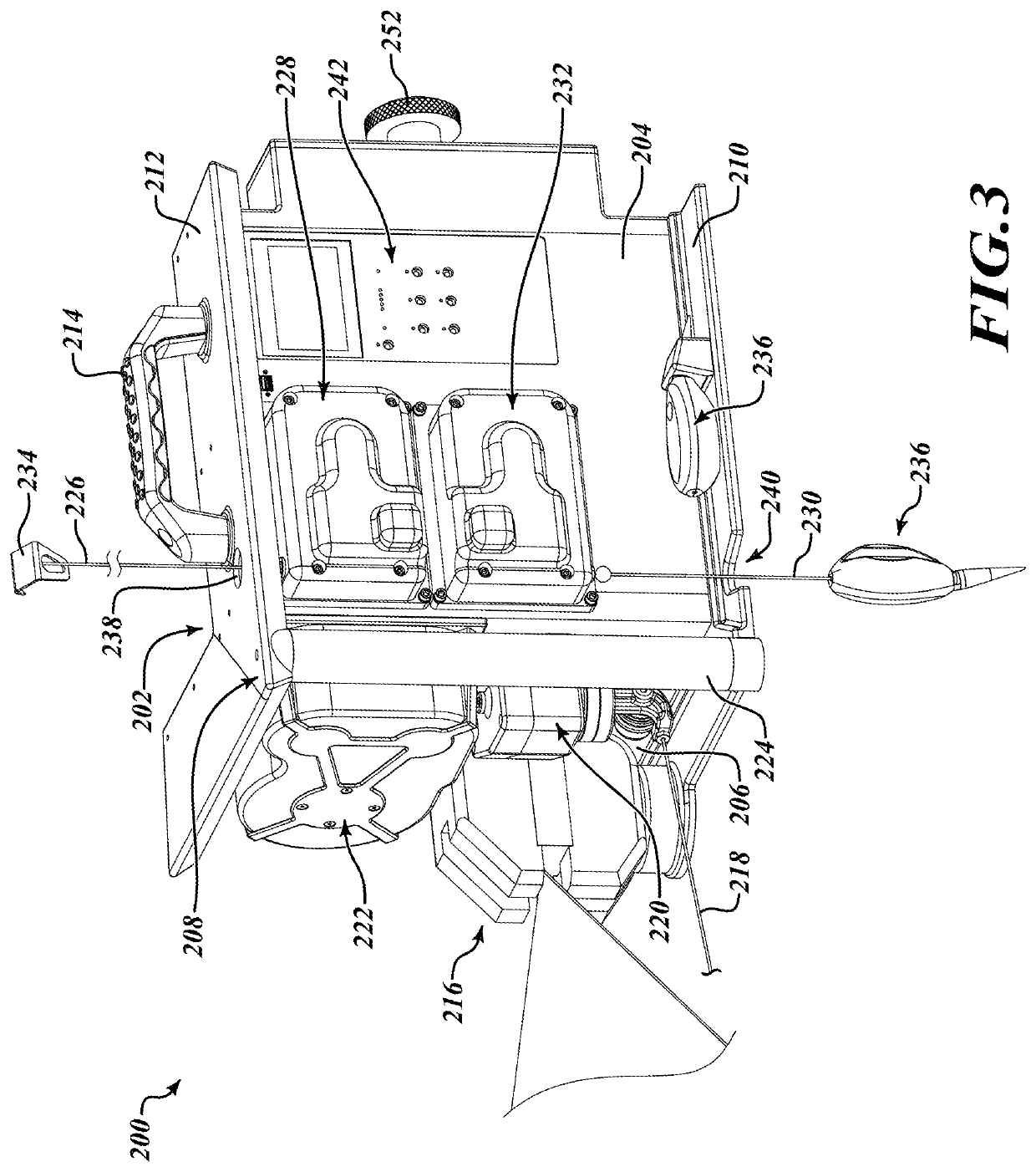
A system for measuring fence posts in a fence run includes a leading unit and a trailing unit. The leading unit includes a first measurement wire extending through a first rotary encoder and terminating in a second rotary encoder, a second measurement wire terminating in a third rotary encoder, and a third measurement wire terminating in a fourth rotary encoder, as well as a clamp to secure the leading unit to a fence post. The trailing unit includes a first rotary encoder to engage with the first measurement wire of the leading unit and a measurement wire terminating in a second rotary encoder, as well as a clamp to secure the trailing unit to a fence post.

Description

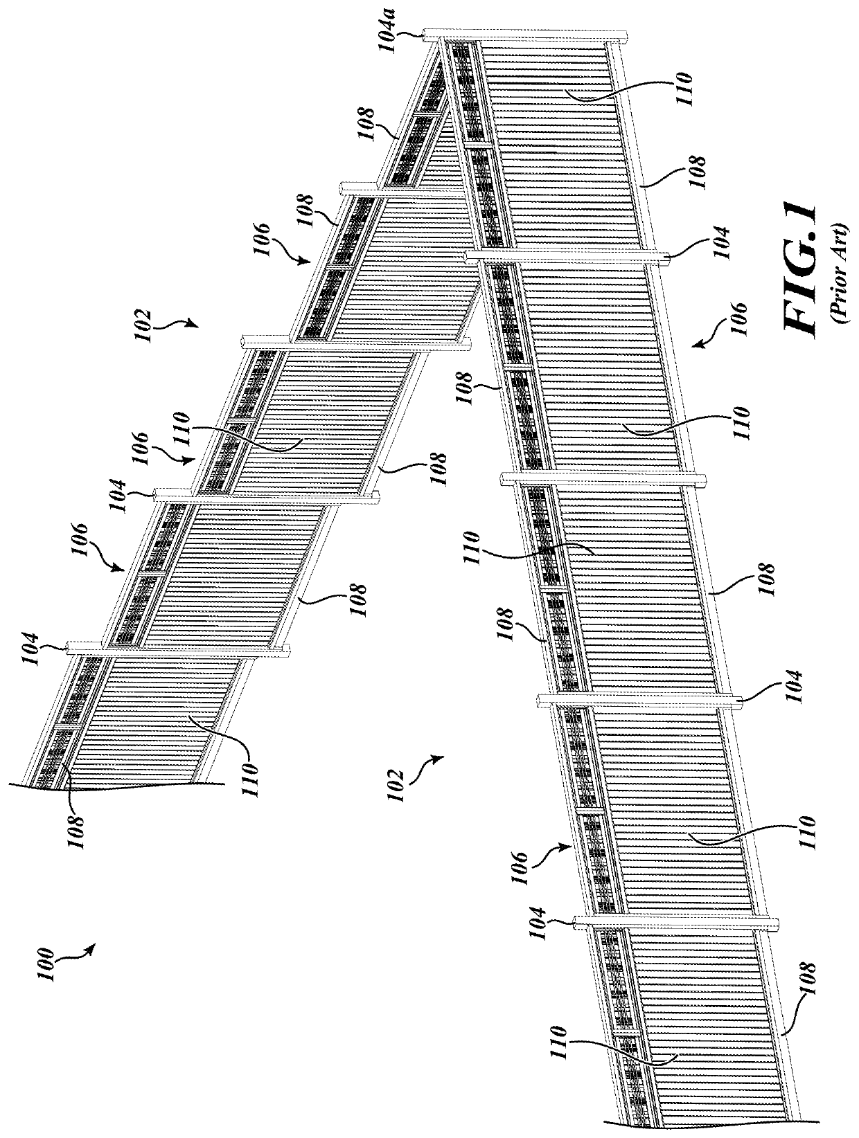
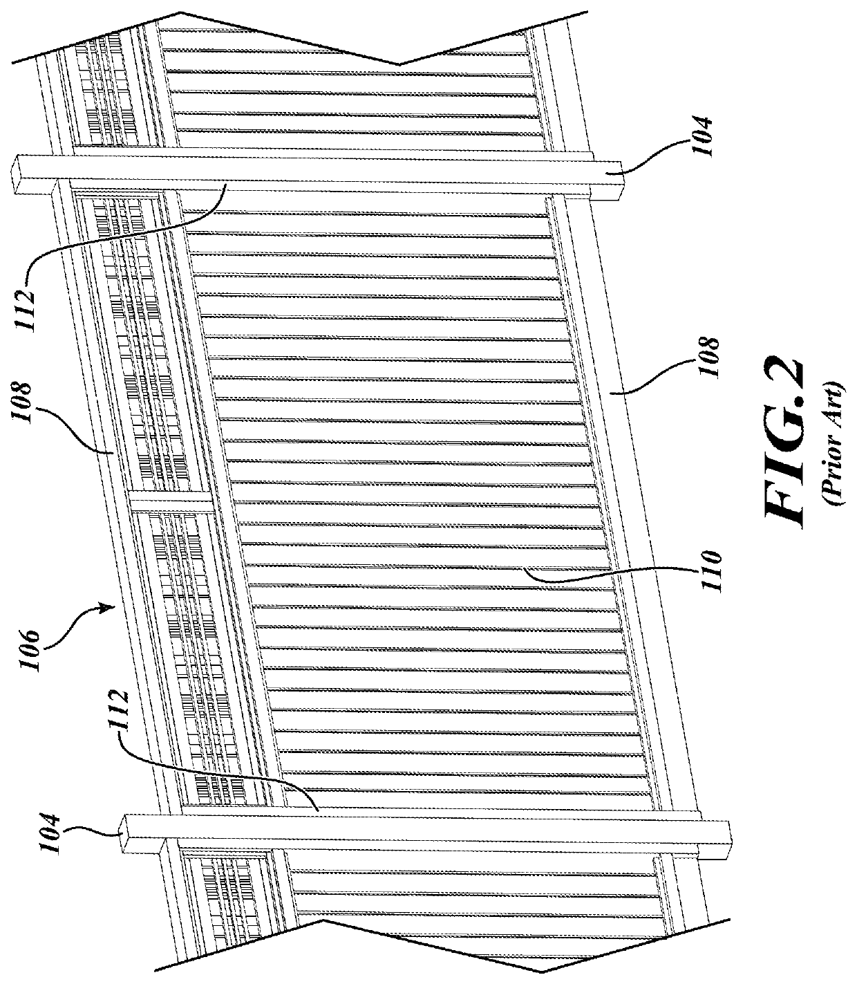
BACKGROUNDTechnical Field[0001]The present disclosure relates generally to fences and other upright structures such as handrails or guardrails, and more particularly to fence posts and systems and methods for taking measurements of fence posts within a fence run.Description of the Related Art[0002]Fences are ubiquitous in modern society, used in a vast range of applications, to mark and accent boundaries, provide security, and control movement of people and animals. Thousands of miles of new and replacement fences are installed every year in the U.S., and utilize vast amounts of construction-related natural resources.[0003]FIG. 1 shows a landscape with a fence 100 extending along portions thereof. The fence 100 shown in FIG. 1 comprises two major segments, or runs, 102. A run is a section or portion of a fence that extends between natural dividing points such as corners, gates, buildings, etc. Except where a fence is attached to a building, each run 102 generally has a terminal post...

Claims


Application Information

Patent Timeline
IPC IPC(8): G01B21/22E04H17/26G01C9/02
CPCG01B21/22E04H17/20G01C9/02E04H17/26G01B5/063G01B5/14G01B5/25G01B3/11G01C15/10
Inventor KNUDSEN, N. ERIC
Owner KNUDSEN N ERIC
Learn More