
Electric height control device

a height control device and electric technology, applied in the direction of resilient suspensions, vehicle springs, vehicle components, etc., can solve the problems of difficult to apply the installation structure to other types of vehicles, difficult to install and connect the components in the vehicle with spatial constraints, etc., to reduce the volume of the module, reduce the development cost, and ensure the effect of safety

Active Publication Date: 2021-07-01
HYUNDAI MOBIS CO LTD
View PDF0 Cites 0 Cited by
  • Summary
  • Abstract
  • Description
  • Claims
  • Application Information

AI Technical Summary

Benefits of technology

The patent is about a device that controls the height of a vehicle's exhaust gases. The device is made up of different parts that are all integrated into one module. This makes it easier to install and reduces the cost of development. The module can be applied to different types of vehicles, and the motor driving part is inserted into a hole in the oil storage part, which makes the device smaller and more compact. The technical effect of this patent is to provide a versatile and cost-effective solution for controlling the exhaust gas height of vehicles.

Problems solved by technology

First, when an electronic control unit generates a control signal, a compressor compresses air and supplies the compressed air to a bellows-type air spring fixed to a vehicle body.
However, since the components of the hydraulic system are separately disposed, the hydraulic system has a problem in that it is difficult to install and connect the components in the vehicle with spatial constraints.
Furthermore, such an installation structure is difficult to apply to other types of vehicles.

Method used


Image

  • Electric height control device
  • Electric height control device
  • Electric height control device

Examples


Embodiment Construction

[0027]Hereinafter, an electric height control device will be described below with reference to the accompanying drawings through various exemplary embodiments. It should be noted that the drawings are not to precise scale and may be exaggerated in thickness of lines or sizes of components for descriptive convenience and clarity only. Furthermore, the terms as used herein are defined by taking functions of the invention into account and can be changed according to the custom or intention of users or operators. Therefore, definition of the terms should be made according to the overall disclosures set forth herein.

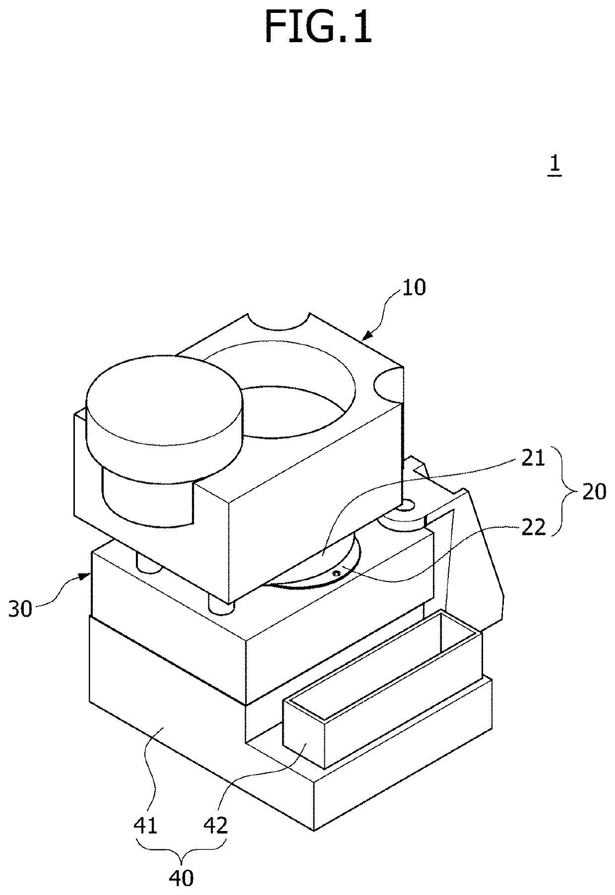
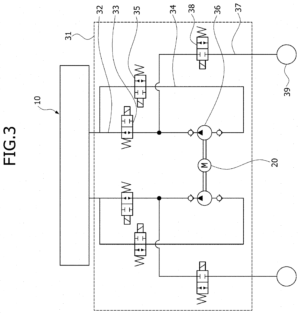
[0028]FIG. 1 is a diagram schematically illustrating an electric height control device in accordance with an embodiment of the present disclosure. Referring to FIG. 1, the electric height control device 1 in accordance with the embodiment of the present disclosure includes an oil storage part 10, a motor driving part 20, a hydraulic block part 30 and a control part 40. Such c...


PUM


Abstract

An electric height control device may include: an oil storage part configured to store oil therein; a motor driving part inserted into the oil storage part and driven when power is applied thereto; a hydraulic block part coupled to the motor driving part, connected to the oil storage part, and configured to amplify oil; and a control part coupled to the hydraulic block part, and configured to control the motor driving part and the hydraulic block part.

Description

CROSS-REFERENCE TO RELATED APPLICATION[0001]This application claims priority from the benefit of Korean Patent Application No. 10-2019-0175352, filed on Dec. 26, 2019, which is hereby incorporated by reference for all purposes as if set forth herein.BACKGROUNDField[0002]Exemplary embodiments of the present disclosure relate to an electric height control device, and more particularly, to an electric height control device whose individual components are integrated into one module to smoothly configure a mounting package and to reduce a development cost.Discussion of the Background[0003]In general, a suspension system refers to a system that relieves shock or vibration applied from the road during driving, thereby improving the ride quality and stability of a vehicle. The suspension system includes a chassis spring, a shock absorber for improving the ride quality by controlling the natural vibration of the chassis spring, and a stabilizer for preventing rolling of the vehicle.[0004]The...

Claims


Application Information

Patent Timeline
Patent Type & Authority Applications(United States)
IPC IPC(8): B60G17/015
CPCB60G17/0152B60G2204/4502B60G2800/914B60G2500/30B60G2202/413B60G2206/016B60G2202/154B60G2204/20B60G17/0408B60G2500/203B60G17/015B60G17/056B60G2800/01
Inventor LEE, SANG MOON
Owner HYUNDAI MOBIS CO LTD
Learn More