
Lubricant supported electric motor including a bearing structure

Pending Publication Date: 2021-04-08
NEAPCO INTPROP HLDG LLC
View PDF8 Cites 1 Cited by
  • Summary
  • Abstract
  • Description
  • Claims
  • Application Information

AI Technical Summary

Benefits of technology

The invention is about a special type of electric motor that uses a lubricant to make it smoother for the rotor to move. This design is strong and sturdy, making it ideal for use in high-shock and high-vibration environments. Additionally, it's more efficient than other motors, meaning it can produce more power with less energy. The motor has a bearing structure that helps keep everything aligned properly, and it's designed to be light and compact.

Problems solved by technology

While each of these motor configurations result in a smaller size and lighter weight arrangement as compared to the prime movers based on the internal combustion engine, they each have certain drawbacks and disadvantages.
For example, the utilization of traction motors as the “on wheel”, “in wheel” or “near wheel” configuration still results in motors that are too heavy and not robust enough to shock loading to be useful for wheel-end applications.
These traction motors also must be supported by rolling element bearings typically at each end of the electric motor shaft, making them too heavy and large to be practical for wheel end applications.
These conventional rolling element bearings also have limited ability to sustain (absorb) large, sudden shocks and also consume significant space within the electric motor that does not contribute to torque production.
Similarly, the utilization of a lubricant supported electric motors as the “on wheel”, “in wheel” or “near wheel” motor in an automotive or land vehicle application results in an arrangement with some performance issues when it is subjected to the wide range of dynamic forces encountered during operation at the wide range of speeds encountered in a prime-mover application.
Lubricant supported electric motors also typically do not include rotor and stator structures that are sufficiently designed to function as bearings.

Method used


Image

  • Lubricant supported electric motor including a bearing structure
  • Lubricant supported electric motor including a bearing structure
  • Lubricant supported electric motor including a bearing structure

Examples


Embodiment Construction

[0021]Example embodiments of a lubricant supported electric motor in accordance with the present disclosure will now be more fully described. Each of these example embodiments are provided so that this disclosure is thorough and fully conveys the scope of the inventive concepts, features and advantages to those skilled in the art. To this end, numerous specific details are set forth such as examples of specific components, devices and mechanisms associated with the lubricant supported electric motor to provide a thorough understanding of each of the embodiments associated with the present disclosure. However, as will be apparent to those skilled in the art, not all specific details described herein need to be employed, the example embodiments may be embodied in many different forms, and thus should not be construed or interpreted to limit the scope of the disclosure.

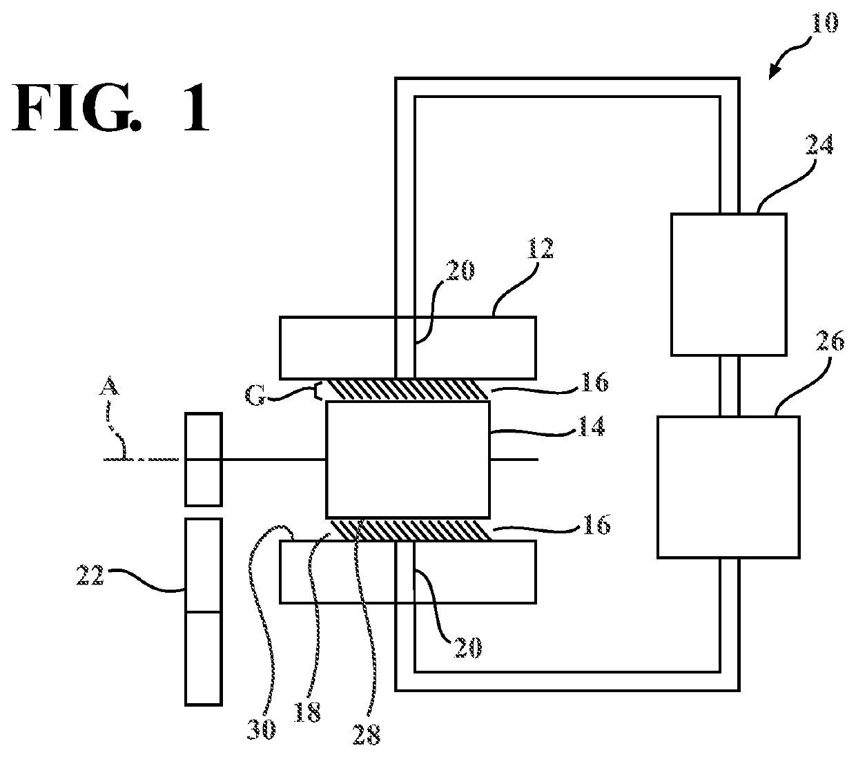
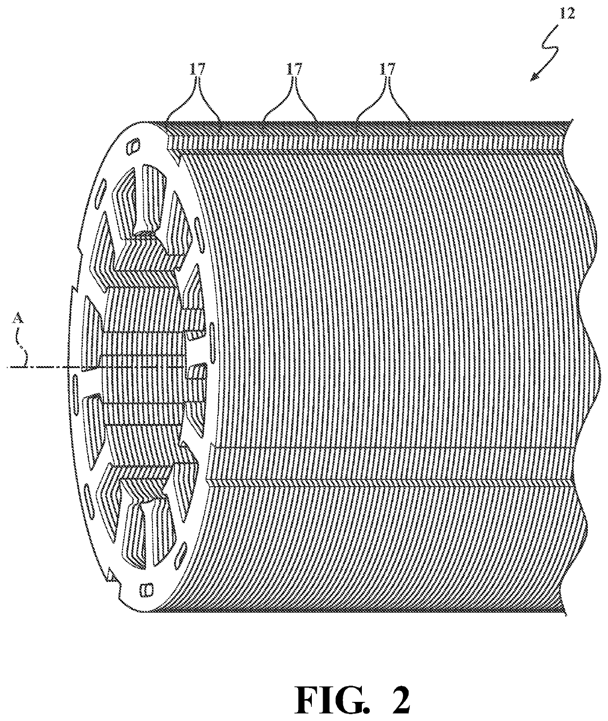
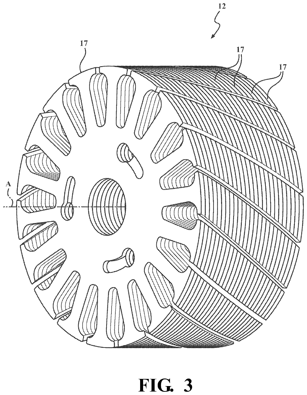
[0022]FIGS. 1 and 4-11 illustrate a lubricant supported electric motor 10 in accordance with an aspect of the disclosu...


PUM


Abstract

A lubricant supported electric motor includes a stator presenting a stator raceway, and a rotor movable relative to the stator about an axis. The rotor presents a rotor raceway disposed in radially spaced and opposing relationship with the stator raceway to define a gap therebetween. A lubricant is disposed in the gap for supporting the rotor relative to the stator. The stator raceway includes a bearing structure comprised of a plurality of hydrodynamic surfaces aligned in parallel relationship along the stator raceway and a plurality of hydrostatic pockets disposed in radially recessed relationship relative to the hydrodynamic surfaces.

Description

CROSS-REFERENCE TO RELATED APPLICATION[0001]The subject application claims priority to U.S. Provisional Application Ser. No. 62 / 912,130 filed on Oct. 8, 2019, the entire disclosure of which is incorporated herein by reference.FIELD OF THE INVENTION[0002]The present disclosure relates to electric devices, such as electric motors and electric generators. More particularly, the present disclosure relates to a lubricant supported electric motor.BACKGROUND OF THE INVENTION[0003]This section provides a general summary of background information and the comments and examples provided in this section are not necessarily prior art to the present disclosure.[0004]Various drivelines in automotive, truck, and certain off-highway applications take power from a central prime mover and distribute the power to the wheels using mechanical devices such as transmissions, transaxles, propeller shafts, and live axles. These configurations work well when the prime mover can be bulky or heavy, such as, for...

Claims


Application Information

Patent Timeline
IPC IPC(8): H02K9/193
CPCH02K9/193H02K7/088H02K5/1677
Inventor REMBOSKI, DONALDDEDO, JACQUELINEVERSTEYHE, MARKLEQUESNE, BRUNO
Owner NEAPCO INTPROP HLDG LLC
Learn More