
Collapsible Pushup Bar

a push-up bar and collapsible technology, applied in the field of collapsible push-up bars, can solve the problems of not being able to easily collapse and disassemble the parts of the push-up bars, not being able to be used regularly, and being unable to be used in regular exercis

Active Publication Date: 2020-10-15
KENSUI LLC
View PDF0 Cites 5 Cited by
  • Summary
  • Abstract
  • Description
  • Claims
  • Application Information

AI Technical Summary

Benefits of technology

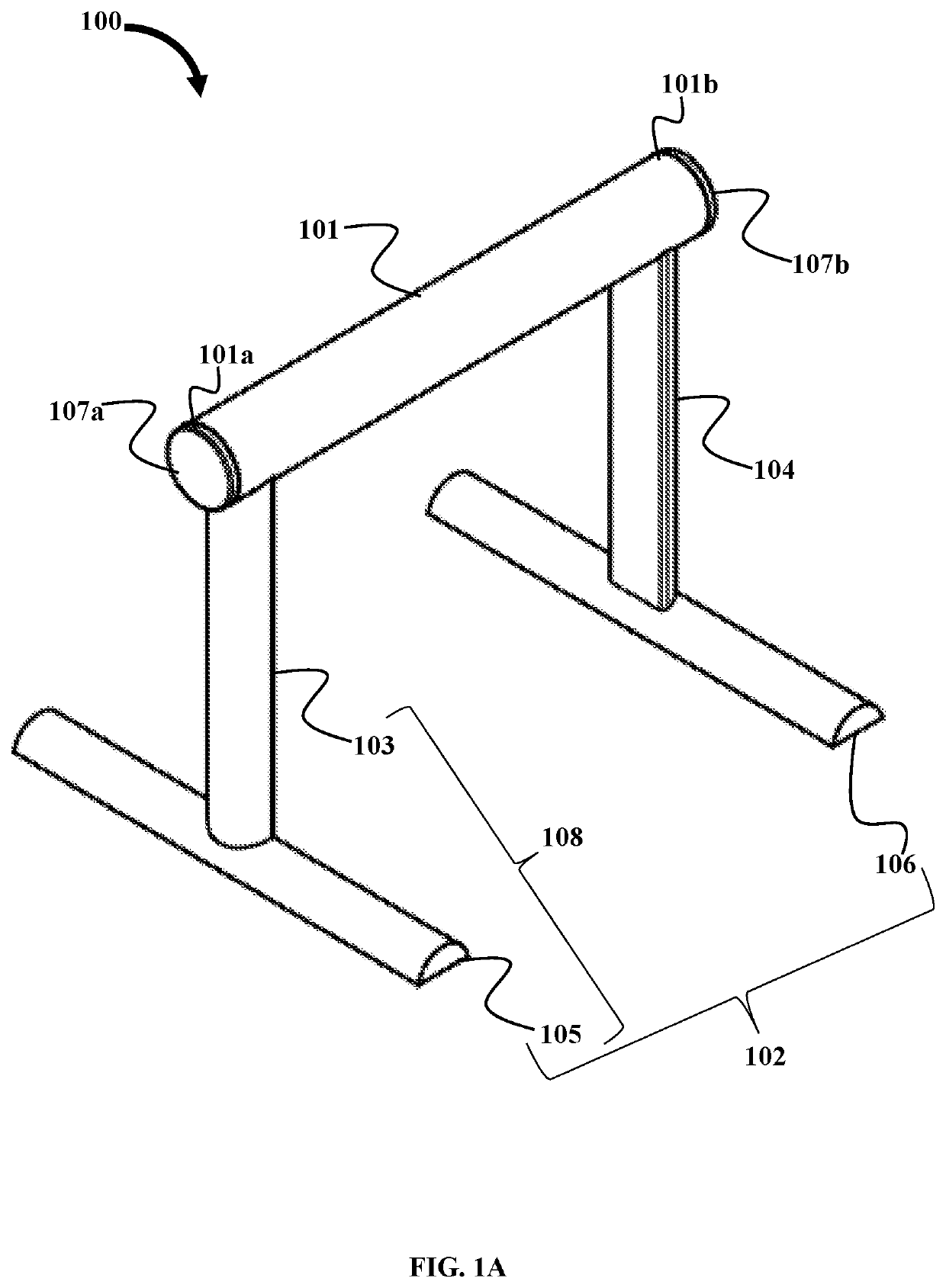
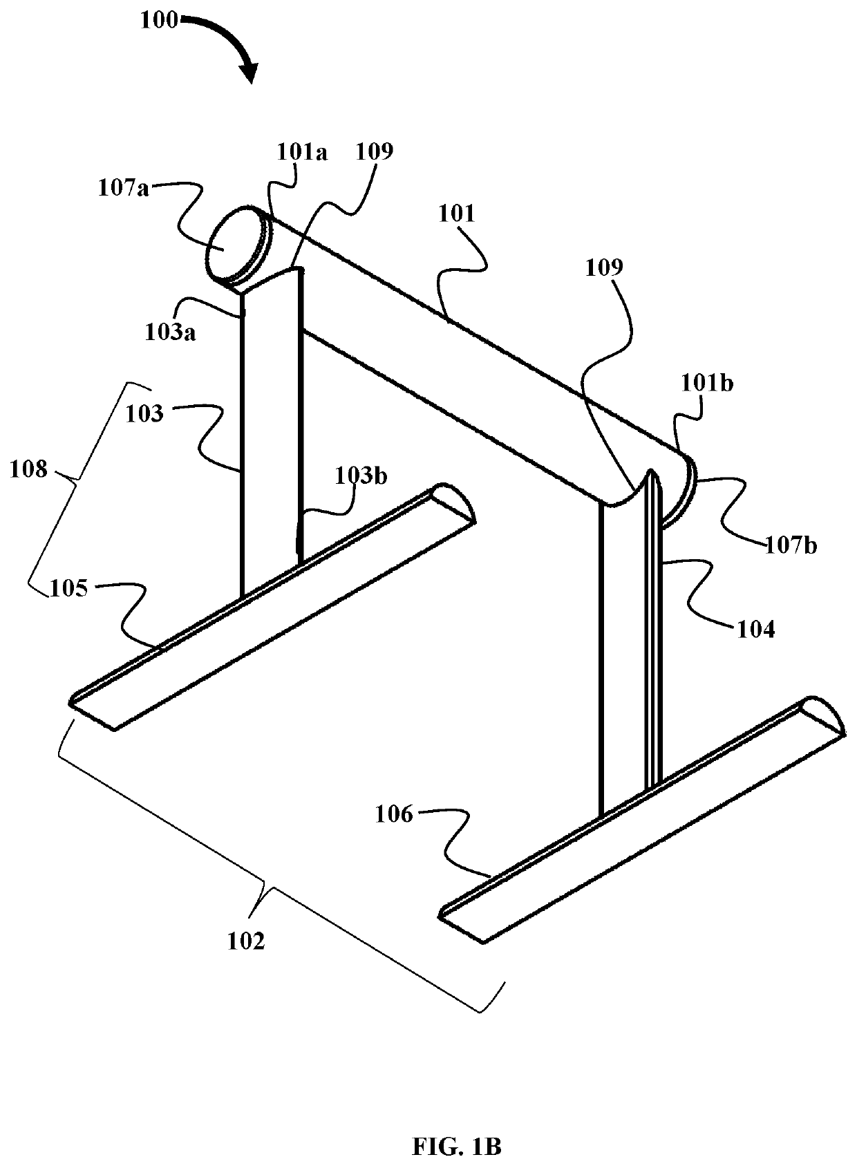
This patent describes a collapsible push-up bar that has a hollow main shaft and a removable leg assembly. The collapsible push-up bar has first and second end-caps that close the ends of the hollow main shaft to prevent the support legs from falling out. The hollow main shaft can be elliptical in cross section. The collapsible push-up bar also includes engagement devices that secure the support legs to the collapsible push-up bar. The engagement devices can be threaded holes or receptacles for button type snap fit fasteners. The technical effects of this invention include a collapsible push-up bar that is easy to assemble, disassemble, and transport.

Problems solved by technology

The busy lifestyle of persons does not permit users to regularly go out and exercise at gymnasiums and other health clubs.
Push-up bars, also called parallettes, that are available in the market are bulky, not portable, and do not allow the push-up bar to be collapsed and the disassembled parts to be compactly stored, for example, within a main bar of the push-up bar.

Method used


Image

  • Collapsible Pushup Bar
  • Collapsible Pushup Bar
  • Collapsible Pushup Bar

Examples


first embodiment

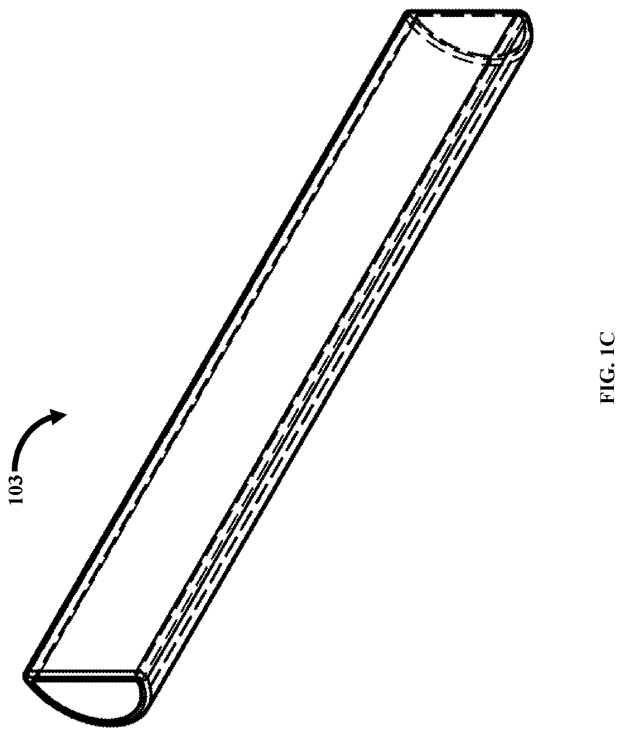
[0049]In the first embodiment, each of the vertical support bars 103 and 104 of the support legs 108 is securely connected to the engagement device 109 of the hollow main shaft 101 prior to the user performing push-ups. Furthermore, the leg assembly 102 is insertable into the hollow main shaft 101, as illustrated in FIG. 1G, by aligning the vertical support bars 103 and 104 with the engagement devices 109 of the hollow main shaft 101 along the axis A-A′ and axis B-B′. The first ends 103a and 104a of the aligned vertical support bars 103 and 104 are then inserted into the engagement devices 109, respectively. The horizontal support bars 105 and 106 are removably secured to the vertical support bars 103 and 104, respectively, as illustrated in FIG. 1G. Each of the horizontal support bars 105 and 106 comprise a receiver slot 105a and 106a in a mid-section of the horizontal support bars 105 and 106, as illustrated in FIGS. 1H and 1I, for receiving the vertical support bars 103 and 104. ...

second embodiment

[0062]The vertical support bars 402 and 403 are removably secured to horizontal support bars 404 and 405, respectively, as shown in FIGS. 4A and 4B. As shown in FIG. 4C, the horizontal support bar 404 comprise a slot 407 configured to removably receive the bottom distal end of the vertical support bar 402. As shown in FIG. 4D, the hollow main shaft 401 comprises engagement devices 409a and 409b that are configured to removably receive the top distal ends of the vertical support bars 402 and 403. The hollow main shaft 401 comprises engagement devices 409a and 409b that are semicircular in form to receive the vertical support bars 402 and 403. In an embodiment, the hollow main shaft 401 comprises notches 410 for securing the vertical support bars 402 and 403 to the hollow main shaft 401, similar to the second embodiment illustrated in FIGS. 2A-2F.

[0063]In an embodiment, the push-up bar 400 is about 75 mm to about 250 mm in height. The vertical support bars 402 and 403 are about 55 mm ...


PUM


Abstract

A collapsible push-up bar comprises a hollow main shaft and a leg assembly. The collapsible push-up bar is, for example, a pair of push up bars which are modular and portable. The collapsible push-up bar is used for exercising, gymnastics and calisthenics. The hollow main shaft comprises one or more engagement devices that are disposed on a length of the hollow main shaft. The hollow main shaft is configured to be held by a user during a workout. The leg assembly comprises one or more support legs, insertable within the hollow main shaft and configured to be removably secured to the engagement device within the hollow main shaft.

Description

CROSS-REFERENCE TO RELATED APPLICATIONS[0001]This application claims priority to and the benefit of the provisional patent application titled “Nanobars”, application No. 62 / 831,270, filed in the United States Patent and Trademark Office on Apr. 9, 2019. The specification of the above referenced patent application is incorporated herein by reference in its entirety.BACKGROUND[0002]The busy lifestyle of persons does not permit users to regularly go out and exercise at gymnasiums and other health clubs. This creates a demand for portable fitness equipment that allow users to exercise at locations other than a gymnasium, for example at their residence, in their office, etc. Many types of portable fitness equipment is available in the market, for example, jump ropes, resistance bands, suspension trainers, exercise ball, etc. Push-ups are a common exercise that persons engage in both for exercises and also for gymnastics and calisthenics. Push-ups are optionally performed on equipment pro...

Claims


Application Information

Patent Timeline
Patent Type & Authority Applications(United States)
IPC IPC(8): A63B23/12A63B21/00
CPCA63B23/1236A63B2210/50A63B21/00047A63B2209/00
Inventor SASANO, REMY
Owner KENSUI LLC
Learn More