
Method for displaying images of a camera system of a vehicle

a camera system and vehicle technology, applied in the field of vehicle camera system display, can solve the problems of unnecessarily detected data, complex display, and excessive computing time for the driver of the vehicl

Inactive Publication Date: 2020-08-20
ROBERT BOSCH GMBH
View PDF0 Cites 0 Cited by
  • Summary
  • Abstract
  • Description
  • Claims
  • Application Information

AI Technical Summary

Benefits of technology

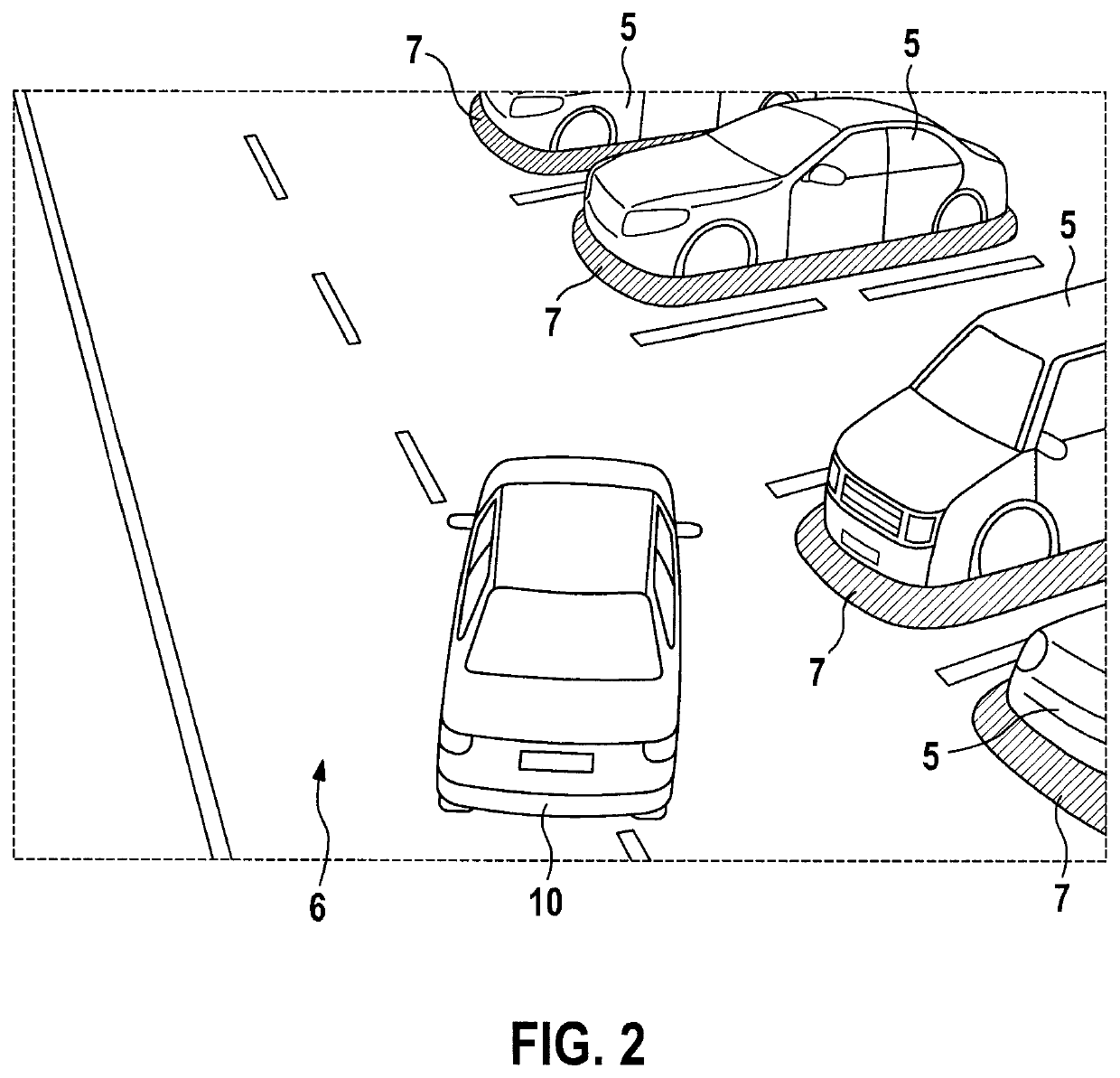
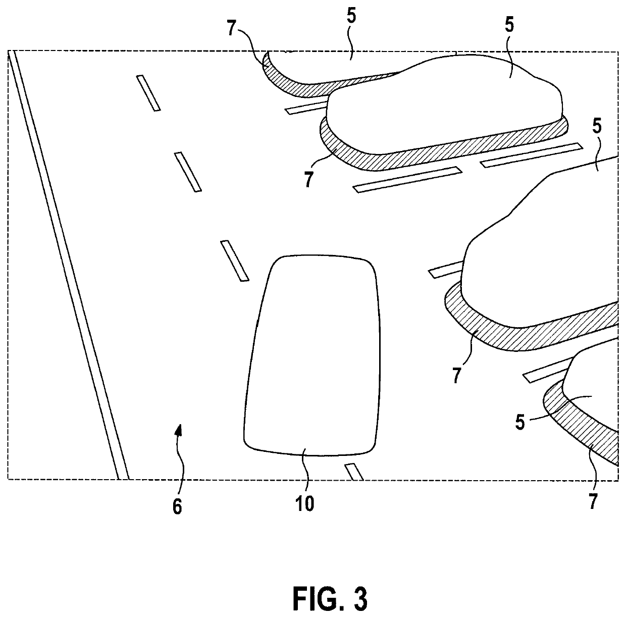
The present invention provides a method for displaying information in different ways, based on a selection criterion. This allows for display of only relevant information to the driver, while reducing the processing power required. The method allows for depiction of obstacles detected by a camera system of a vehicle in a virtual three-dimensional space, providing a realistic view of the surroundings to the driver. By using predefined textures and eliminating actual textures generated by the camera system, the information content of the depiction is reduced while the required processing power is significantly reduced. This enables a focus on relevant pieces of information for the driver and reduces the processing power required.

Problems solved by technology

Due to the variety of pieces of information which are to be displayed by the SVS, the driver of the vehicle may be overwhelmed if they are not displayed appropriately.
This has the result that data are unnecessarily detected which do not supply additional value to the driver, since he / she does not recognize these pieces of information.
At the same time, a very complex display is conventionally produced with substantial computing time, which integrates all pieces of information available to the surround view system in one display image.
The driver of the vehicle may thus unambiguously recognize where obstacles are located in the surroundings, and whether these obstacles represent a hazard to his vehicle.

Method used


Image

  • Method for displaying images of a camera system of a vehicle
  • Method for displaying images of a camera system of a vehicle
  • Method for displaying images of a camera system of a vehicle

Examples


Embodiment Construction

[0016]Exemplary embodiments of the present invention are described in detail hereafter with reference to the figures.

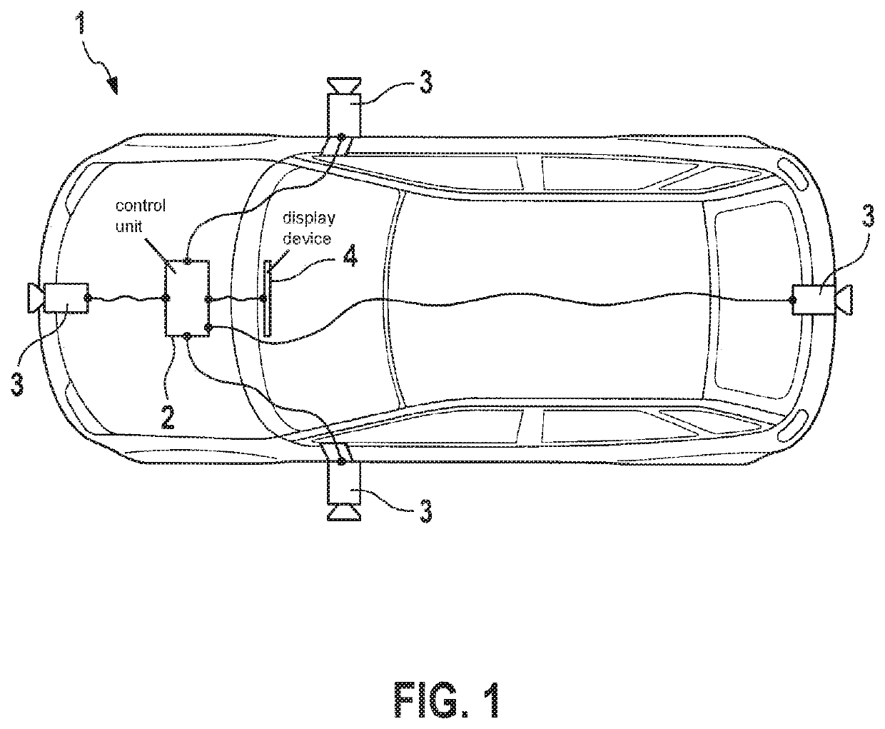
[0017]FIG. 1 shows a schematic view of a vehicle including a control unit for executing a method according to one exemplary embodiment of the present invention.

[0018]FIG. 2 shows a first example of a depiction which is generated with the aid of the method according to the exemplary embodiment of the present invention.

[0019]FIG. 3 shows a second example of a depiction which is generated with the aid of the method according to the exemplary embodiment of the present invention.

[0020]FIG. 4 shows a third example of a depiction which is generated with the aid of the method according to the exemplary embodiment of the present invention.

[0021]FIG. 5 shows a fourth example of a depiction which is generated with the aid of the method according to the exemplary embodiment of the present invention.

DETAILED DESCRIPTION OF EXAMPLE EMBODIMENTS

[0022]FIG. 1 schematically shows a vehi...


PUM


Abstract

A method for displaying images of a camera system of a vehicle. Obstacles detected using the camera system from the surroundings of the vehicle are depicted on a display device in a virtual three-dimensional space as virtual three-dimensional objects, and it is established on the basis of a selection criterion whether the virtual three-dimensional objects and / or the virtual three-dimensional space are covered using textures which are generated by the camera system or are covered using at least one predefined texture.

Description

FIELD[0001]The present invention relates to a method for displaying images of a camera system of a vehicle. In particular, the camera system is a panorama view system, which may detect images all around a vehicle.BACKGROUND INFORMATION[0002]Panorama view systems are known as surround view systems (SVS) in the related art. Such systems use various data types to display a maximum number of pieces of information. In this way, the maximum number of pieces of information which the system may provide is displayed to the driver. Such data types may be obtained in particular from sensor data fusions, from pieces of information of a cloud, and from many other sources. Typical data from sensor data fusions include pieces of information about occupied and free areas around the vehicle, which are ascertained with the aid of video sensors, radar sensors, LIDAR sensors, or other surroundings sensors of the vehicle. Pieces of information from a cloud may be in particular weather conditions and ava...

Claims


Application Information

Patent Timeline
IPC IPC(8): H04N13/111H04N13/15G08G1/14H04N13/282H04N5/232B60R1/00
CPCH04N5/23238G08G1/143B60R2300/307H04N13/111B60R2300/20H04N13/15H04N13/282B60R2300/10B60R1/00G06T15/04G06T19/20G06T2219/004B60R1/27H04N23/698
Inventor ESPARZA GARCIA, JOSE DOMINGOCANO, RAPHAEL
Owner ROBERT BOSCH GMBH
Learn More