Elastically deformable wound dressings
a wound dressing and elastic technology, applied in the field of tissue treatment, to achieve the effect of reducing edema, minimizing edema, and reducing edema for tissue sites
- Summary
- Abstract
- Description
- Claims
- Application Information
AI Technical Summary
Benefits of technology
Problems solved by technology
Method used
Image

Examples
example 1
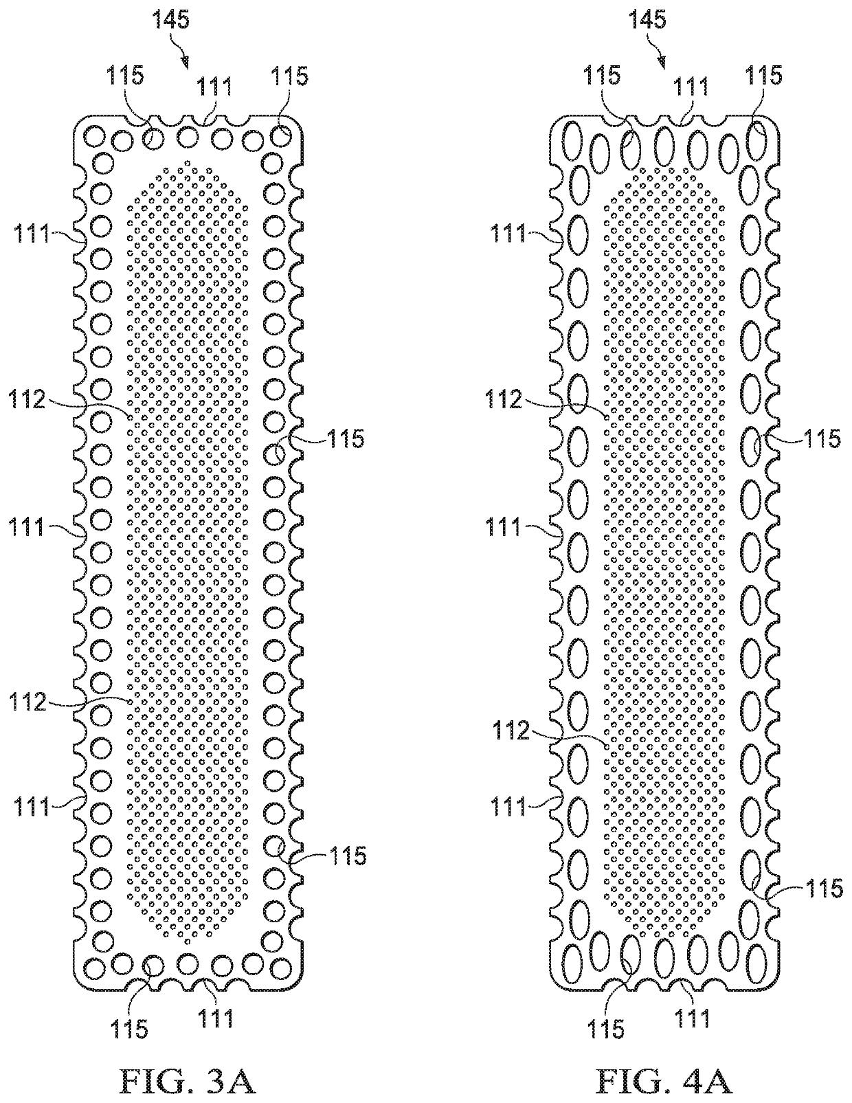
[0108]FIG. 3A shows an example of a silicone layer 145 that may be associated with some embodiments of the dressing layer 110. As illustrated in FIG. 3A, some embodiments of the silicone layer 145 may be perforated. The silicone layer 145 of FIG. 3A includes central perforations 112 having a roughly circular shape. The silicone layer 145 may also have margin perforations 115, which may also exhibit a roughly circular shape. In some embodiments, the margin perforations 115 may be considerably larger than the central perforations 112. The silicone layer 145 of FIG. 3A also has edge cuts 111, each of the edge cuts 111 having a semi-circular shape.
[0109]FIG. 3B is an exploded view illustrating additional details that may be associated with some examples of the dressing 100 with the silicone layer 145 of FIG. 3A. FIG. 3B also illustrates an embodiment of the backing layer 120, below which an example of an absorbent layer 160 is shown to be disposed, defining a backing layer margin 125. A...
example 2
[0110]FIG. 4A shows another example of the silicone layer 145 that may be associated with some embodiments of the dressing layer 110. As illustrated in FIG. 4A, some embodiments of the silicone layer 145 may be perforated. The silicone layer 145 of FIG. 4A includes central perforations 112 having a roughly circular shape. The silicone layer 145 may also have margin perforations 115, which may exhibit a roughly oval shape. In some embodiments, the margin perforations 115 may be considerably larger than the central perforations 112. The silicone layer 145 of FIG. 4A also has edge cuts 111, each of the edge cuts 111 having a semi-circular shape.
[0111]FIG. 4B is an exploded view illustrating additional details that may be associated with an example embodiment of the dressing 100 with the perforated silicone layer 145 of FIG. 4A. FIG. 4B also illustrates an example of the backing layer 120, below which an example of the absorbent layer 160 is shown to be disposed, defining a backing laye...
example 3
[0112]FIG. 5A shows another example of the silicone layer 145 that may be associated with some embodiments of the dressing layer 110. As illustrated in FIG. 5A, some embodiments of the silicone layer 145 may be perforated. The silicone layer 145 includes central perforations 112 having a roughly circular shape. The silicone layer 145 may also have margin perforations 115 having a roughly triangular shape, alternating in orientation such that triangular sides and triangular point are alternately proximal to each other. In some embodiments, the margin perforations 115 may be considerably larger than the central perforations 112. The silicone layer 145 of FIG. 5A also has edge cuts 111, each having a shape that is roughly half the margin perforations 115 and reflecting the same orientation or pattern.
[0113]FIG. 5B is an exploded view showing additional details that may be associated with some examples of the dressing 100 with the silicone layer 145 of FIG. 5A. FIG. 5B also illustrates ...
PUM
| Property | Measurement | Unit |
|---|---|---|
| surface area | aaaaa | aaaaa |
| elongation | aaaaa | aaaaa |
| elongation | aaaaa | aaaaa |
Abstract
Description
Claims
Application Information
 - R&D
- Intellectual Property
- Life Sciences
- Materials
- Tech Scout
- Unparalleled Data Quality
- Higher Quality Content
- 60% Fewer Hallucinations
Browse by: Latest US Patents, China's latest patents, Technical Efficacy Thesaurus, Application Domain, Technology Topic, Popular Technical Reports.
© 2025 PatSnap. All rights reserved.Legal|Privacy policy|Modern Slavery Act Transparency Statement|Sitemap|About US| Contact US: help@patsnap.com