Centrifugal pump

Active Publication Date: 2019-10-17
GRUNDFOS HLDG
View PDF0 Cites 0 Cited by
  • Summary
  • Abstract
  • Description
  • Claims
  • Application Information

AI Technical Summary

Benefits of technology

The invention is a solution for shaft seal arrangements in pumps and other machinery. The solution involves providing a fluid already on the seal arrangement, preventing it from becoming too dry when the assembly is started. This means that special treatment of the seal arrangement before starting is not required. The method also allows the seal arrangement to be filled with fluid during assembly, making it simple and efficient. The invention also includes a cavity seal with a specific shape that ensures a reliable sealing and allows for a gap formation with a labyrinth effect. The cavity is advantageously located between the shaft projection sleeve, carrier, and stationary slide ring and is connected to the sealing gap through a gap or annular space. Pre-filling the cavity with fluid simplifies the assembly of the seal arrangement without major interventions.

Problems solved by technology

However, the disadvantage with such types of shaft seal arrangements is the fact that since they are lubricated by the delivery fluid of the pump, this delivery fluid must pass through the seal arrangement as quickly as possible on starting operation of the pump, so that the desired lubrication of the shaft seal by the delivery fluid occurs.
If the shaft seal arrangement runs dry, then this is destroyed on its own accord within a very short time due to friction and the development of heat.
Although it is counted as belonging to the state of the art to lubricate such shaft seal arrangements independently of the delivery fluid, however, the effort with regard to design and maintenance is comparatively high due to the fact that on the one hand the lubricant is to be metered accordingly and on the other hand is to be refilled after a certain time.
In particular, a complete fluid pre-filling of the cavity necessitates complicated interventions in the assembly procedure.

Method used


Image

  • Centrifugal pump
  • Centrifugal pump
  • Centrifugal pump

Examples


Embodiment Construction

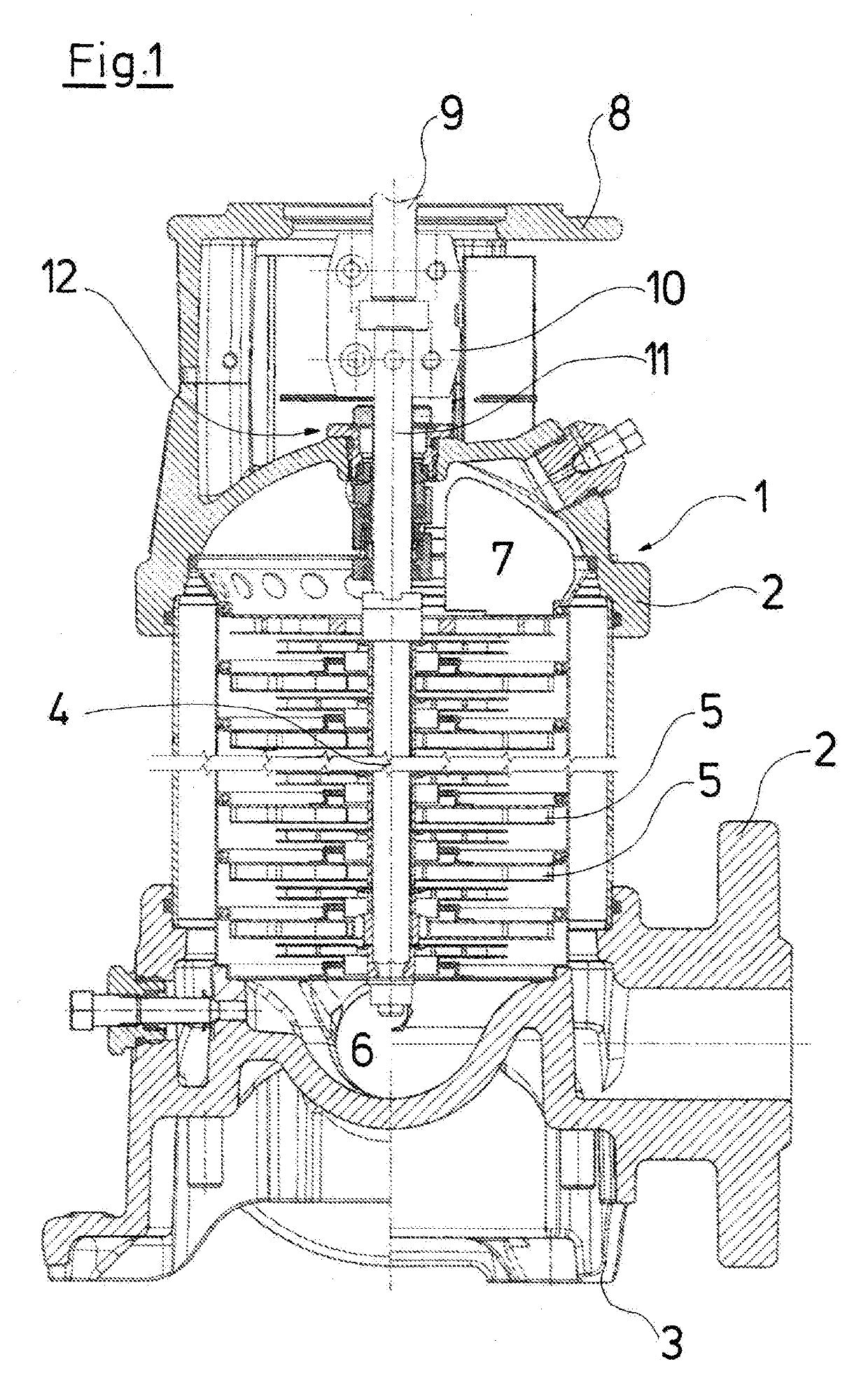
[0043]Referring to the drawings, with regard to the pump represented by way of FIG. 1, a multi-stage centrifugal pump 1, with a pump casing 2 comprises a foot 3, with which the pump casing 2 can be arranged standing on the ground, wherein a shaft 4 which is rotatably mounted within the casing 2 is arranged vertically. The shaft 4 carries a number of impellers 5 corresponding to the number of pump stages. The fluid to be delivered is delivered from the suction port 6 arranged at the end of the shaft which is at the bottom in FIG. 1, upward to a delivery chamber 7, from where it is led to the delivery connection of the pump casing 2. The upper side of the pump casing 2 is configured as a motor base 8 and is envisaged for receiving an electric motor, whose pump-side shaft end 9 via a coupling 10 is rotationally fixedly connected to the end of the shaft 4 which is led upwards out of the actual pump casing 2.

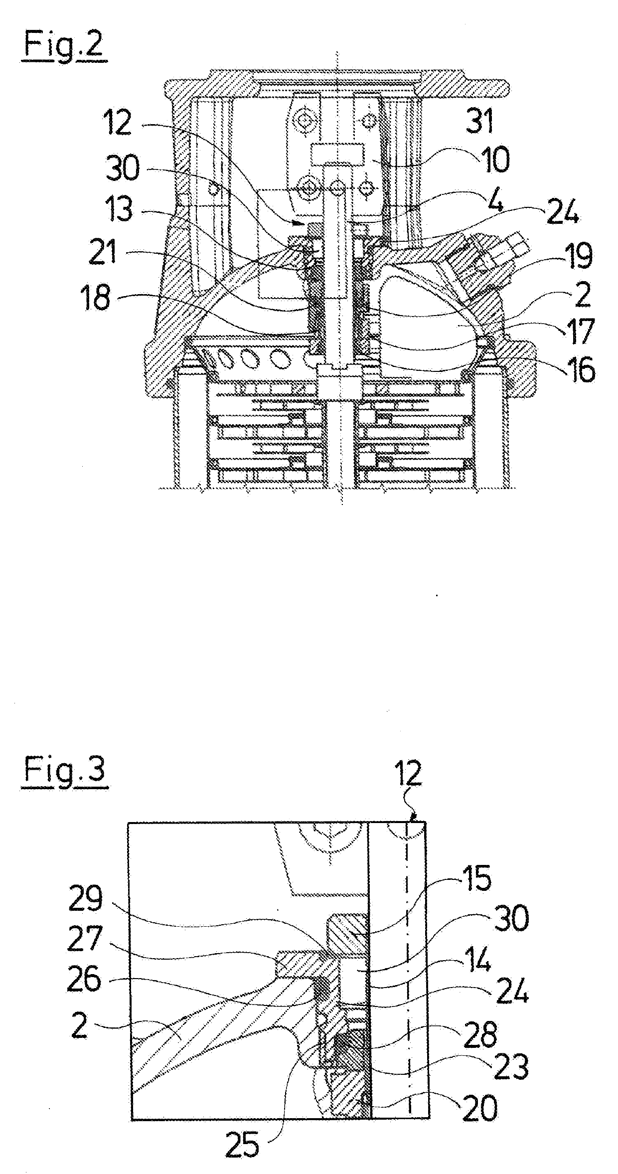
[0044]The pump-side shaft end 11 is led through an opening 13 of the pump casing...


PUM


Abstract

A cartridge seal is provided for sealing a shaft (4) with respect to a housing (2) and is intended to be a slide ring seal arrangement (12) for a centrifugal pump. The cartridge seal includes a shaft protection sleeve which is rotationally connected to the shaft (4) by a retaining ring, a support (24) for incorporating the cartridge seal into a housing opening of the pump housing (2), a slide ring which is rotationally connected to the shaft protection sleeve and a counter slide ring which is rotationally connected to the support (24), as well as an enclosed space (30) within the sealing arrangement. The space (30) is fluidically connected to a sealing gap formed between the slide ring and the counter slide ring, and is at least partially prefilled with liquid in order to prevent dry running when the pump is operated for the first time.

Description

CROSS REFERENCE TO RELATED APPLICATIONS[0001]This application is a United States National Phase Application of International Application PCT / EP2017 / 084339 filed Dec. 22, 2017, and claims the benefit of priority under 35 U.S.C. § 119 of European Application 16 206 579.1, filed Dec. 23, 2016, the entire contents of which are incorporated herein by reference.TECHNICAL FIELD[0002]The invention relates to a method for manufacturing a shaft seal arrangement, in particular on a centrifugal pump for sealing a shaft with respect to a surrounding casing, to a centrifugal pump with such a seal arrangement as well as to a cartridge seal.TECHNICAL BACKGROUND[0003]With centrifugal pumps, it is counted as belonging to the state of the art to seal the delivery-side end of the shaft, on which one or more impellers are seated, with respect to the pump casing, by way of a shaft seal arrangement. Such a seal arrangement comprises a rotating slide ring which co-rotates with the shaft, as well as a stati...

Claims


Application Information

Patent Timeline
IPC IPC(8): F04D29/12F04D1/06F16J15/34
CPCF04D1/06F04D29/12F16J15/3464F04D1/00F04D29/10F04D29/126F04D29/128
Inventor GRANN, HELGENIELSEN, JOHN FRIGÅRDSVARRE, ERIK BUNDESENVEDSTED, PER FROST
Owner GRUNDFOS HLDG
Why Eureka
Try Eureka