
Atomizer and electronic cigarette having same

Active Publication Date: 2019-10-03
SHENZHEN FIRST UNION TECH CO LTD
View PDF0 Cites 6 Cited by
  • Summary
  • Abstract
  • Description
  • Claims
  • Application Information

AI Technical Summary

Benefits of technology

The present disclosure is related to an atomizer and electronic cigarette that can improve tobacco liquid spillage and user experience. The atomizer includes a reservoir for storing tobacco liquid, a gas pathway, an air inlet, and an aerosol outlet. A heater with a hollow atomizing pathway is nested within the gas pathway, and the liquid conductor surrounds the heater to prevent saturation and alleviate leakage. The design allows for easier cleaning and resolution of spillage issues.

Problems solved by technology

However, during the process of inventors' research, one area of particular concern to consumers and inventors is that by transferring the tobacco liquid from the lateral of the liquid conductor to the heater, when a level of the tobacco liquid in the reservoir is higher than the liquid conductor, the liquid conductor is easy to get saturated causing tobacco liquid absorbed in the liquid conductor to be expelled inadvertently from the liquid conductor under gravity force.
Consequently, this transferring technique is cumbersome and results in spillages of tobacco liquid, deteriorating the user experiment.

Method used


Image

  • Atomizer and electronic cigarette having same
  • Atomizer and electronic cigarette having same
  • Atomizer and electronic cigarette having same

Examples


embodiment 1

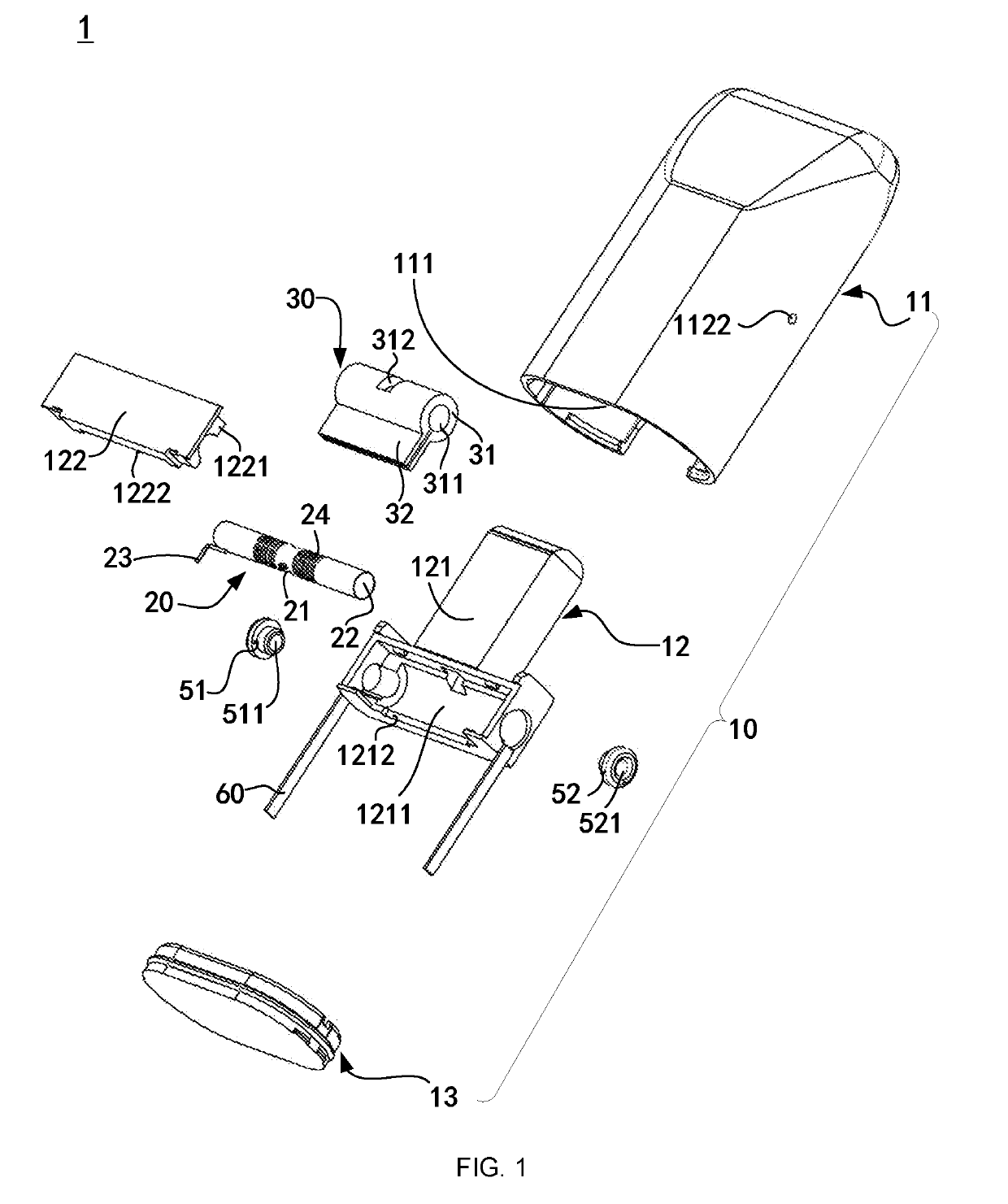
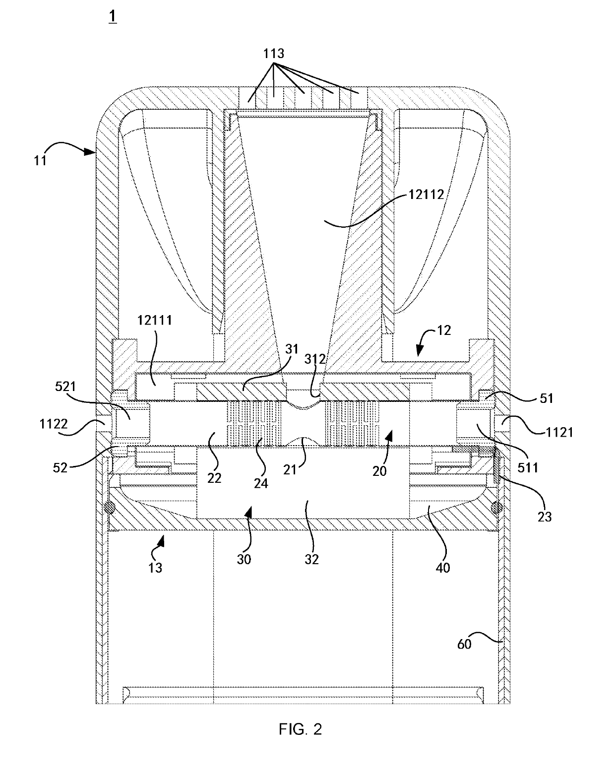
[0069]Referring to FIG. 1 and FIG. 2, which illustrate an atomizer in accordance with an embodiment of the present disclosure. The atomizer 1 includes an atomizing body 10, a heater 20 and a liquid conductor 30. The liquid conductor 30 surrounding the heater 20 together are received in the atomizing body 10.

[0070]More specifically, the atomizing body 10 includes: a shell 11, a fixing component 12 and a base 13.

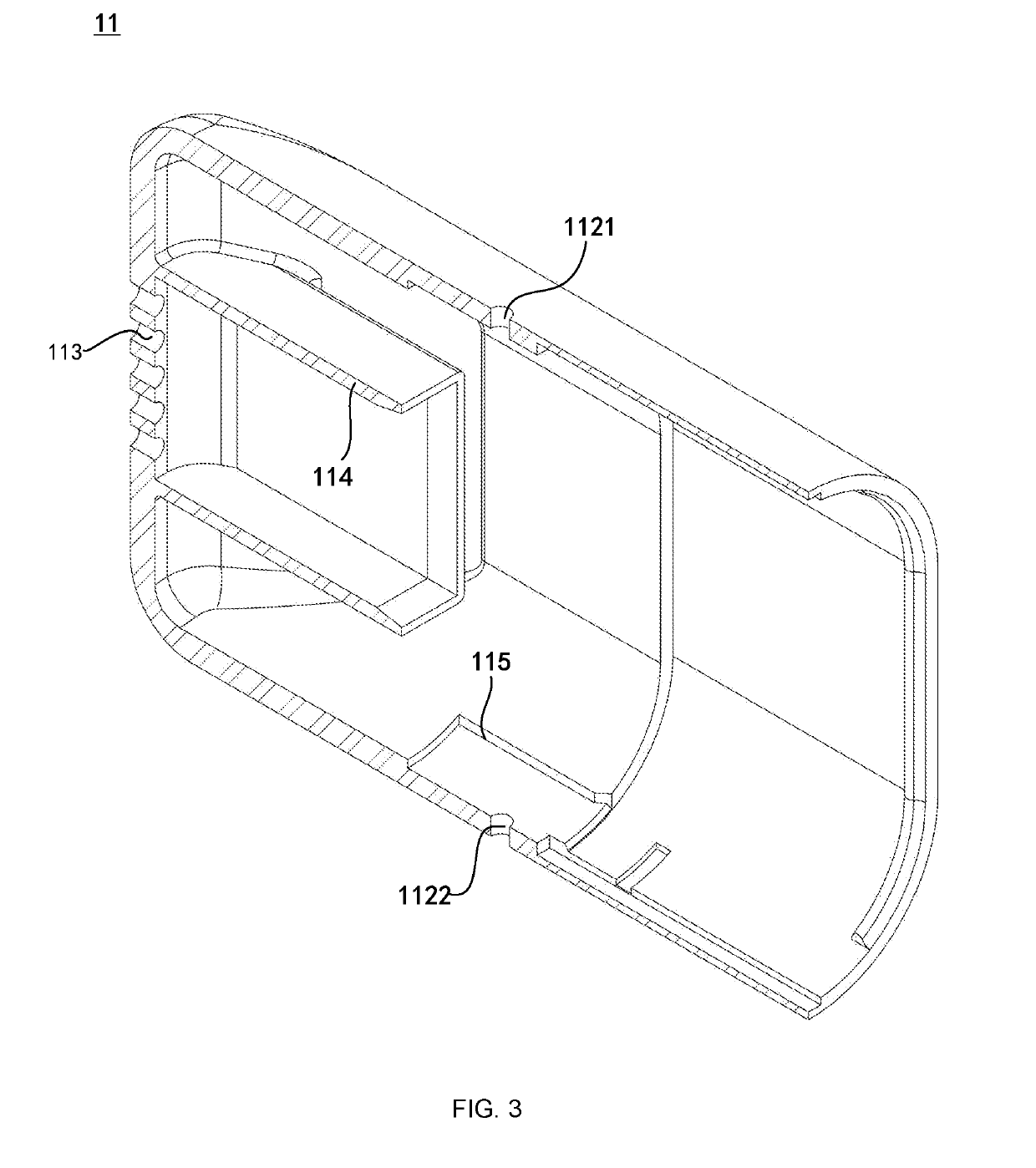
[0071]Referring to FIGS. 1-3, the shell 11 has a receiving chamber 111 that is formed by a sidewall (not shown) and a top wall (not shown) of the shell 11. The sidewall of the shell 11 is bored with an air inlet 112, the air inlet 112 is oriented perpendicular to the sidewall, and the air inlet 112 intercommunicates with the receiving chamber 111. The top wall of the shell 11 is opened with an aerosol outlet 113. The aerosol outlet 113 is oriented perpendicular to the top wall, and the aerosol outlet 113 intercommunicates with the receiving chamber 111, so that exterior air ma...

embodiment 2

[0109]Referring to FIG. 6 and FIG. 7, which illustrate an atomizer in accordance with an embodiment of the present disclosure. The atomizer 1 includes: an atomizing body 10, a heater 20, a liquid conductor 30 and a clamping component 70. The liquid conductor 30 surrounding the heater 20 is received in the clamping component 70 and later on is received in the atomizing body 10 via the clamping component 70.

[0110]More specifically, the atomizing body 10 includes a shell 11, a fixing component 12 and a base 13.

[0111]Referring to FIGS. 6-8, the shell 11 has a receiving chamber 111 formed therein, the receiving chamber 111 is encompassed by a side wall (not shown) and a top wall (not shown). The side wall of the shell 11 is bored with an air inlet 112. The air inlet 112 is perpendicular to the receiving chamber 111 and the air inlet 112 intercommunicates with the receiving chamber 111. The top wall of the shell 11 is bored with an aerosol outlet 113. The aerosol outlet 113 is perpendicul...

embodiment 3

[0147]An electronic cigarette is provided by the present disclosure, the electronic cigarette (not shown) includes a power supply module (not shown) and the aforementioned atomizer (not shown), the power supply module is detachably connected with the atomizer 1.

[0148]More specifically, the power supply module is coupled with the first electrode 23 or the second electrode 25 to supply power to the heater 20 heating the tobacco liquid for atomization.


PUM


Abstract

An atomizer is provided including an atomizing body, having a proximal end, a distal end opposite to the proximal end, a longitudinal axis between the proximal end and the distal end, and a transverse axis perpendicular to the longitudinal axis; an aerosol outlet adjacent to the proximal end of the atomizing body; an air inlet bored at a lateral surface of the atomizing body; a gas pathway within the atomizing body and adjacent to the proximal end of the atomizing body; the gas pathway intercommunicating with the air inlet and the aerosol outlet; a reservoir within the atomizing body and adjacent to the distal end of the atomizing body, the reservoir configured to store tobacco liquid; a heater configured for heating the tobacco liquid to generate an aerosol; the heater being disposed inside the gas pathway; a liquid conductor, extending towards the proximal end of the atomizing body.

Description

TECHNICAL FIELD[0001]The present disclosure relates to the field of electronic cigarettes, and particularly to an atomizer and an electronic cigarette having same.BACKGROUND ART[0002]The electronic cigarette containing tobacco liquid generates an aerosol mist or vapour generated by typically heating the tobacco liquid, generally encompasses a power supply module and an atomizer, of which, the atomizer includes a gas-inlet pathway, a gas-outlet pathway, a heater, a liquid conductor and a reservoir. By means of the liquid conductor, the atomizer transfers the tobacco liquid in the reservoir to the heater for heating and atomizing, exterior air flowing in through the gas-inlet pathway bears the atomized tobacco liquid, then expelled through the gas-outlet pathway to form the aerosol mist or vapour.[0003]In the prior art atomizers with a lower gas-inlet configuration, the liquid conductor surrounding the heater is disposed inside the gas-outlet pathway, the reservoir surrounds the liqui...

Claims


Application Information

Patent Timeline
IPC IPC(8): A24F47/00H05B3/44A24F15/015A24F40/10A24F40/44A24F40/46A24F40/485
CPCA24F47/008H05B2203/021H05B3/44A24F40/46A24F40/10A24F40/44A24F15/015A24F40/485
Inventor FU, JIAQILI, ZHENGFAXU, ZHONGLILI, YONGHAI
Owner SHENZHEN FIRST UNION TECH CO LTD
Learn More