Blood pressure measuring device, blood pressure measuring method and recording medium having blood pressure measuring program recorded therein
a technology of blood pressure measurement and measuring program, which is applied in the field of blood pressure measurement device, blood pressure measurement method, and recording medium having blood pressure measurement program recorded therein, can solve the problem of large burden on the user by method, and achieve the effect of simple blood pressure measuremen
- Summary
- Abstract
- Description
- Claims
- Application Information
AI Technical Summary
Benefits of technology
Problems solved by technology
Method used
Image
Examples
first example embodiment
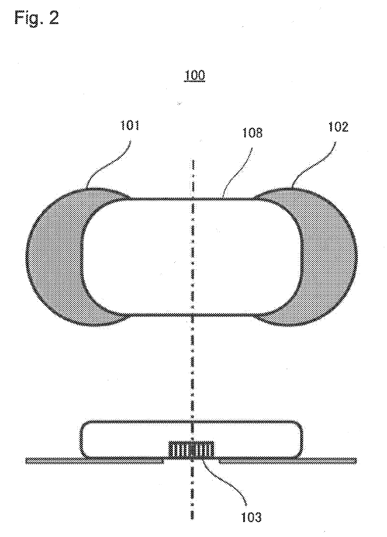
[0034]FIG. 1 is a block diagram of a blood pressure measuring device 100 according to a first example embodiment of the present invention. The blood pressure measuring device 100 includes a first electrode 101, a second electrode 102, a first pulse wave detecting unit 103, an electrocardiogram measuring unit 104, a pulse wave measuring unit 105, and a blood pressure estimating unit 106. FIG. 2 illustrates a plan view and a cross-sectional view of the blood pressure measuring device 100. The reference symbol 108 designates a casing of the blood pressure measuring device 100.
[0035]The first electrode 101 and the second electrode 102 are electrodes for acquiring an electrocardiogram that is a weak electric signal flowing through an entire body. The first electrode 101 and the second electrode 102 are provided at an end portion of the casing 108. Surfaces that belong to the first electrode 101 and the second electrode 102 and that contact with a body surface have an adhesive property, a...
second example embodiment
[0046]FIG. 9 is a block diagram in a second example embodiment of a blood pressure measuring device according to the present invention. A difference from the first example embodiment is that a cuff 109 is used for acquiring a pulse wave. The blood pressure measuring device 100 includes the first electrode 101, the second electrode 102, the cuff 109, a second pulse wave detecting unit 110 connected to the cuff 109, the electrocardiogram measuring unit 104, the pulse wave measuring unit 105, and the blood pressure estimating unit 106. Further, the blood pressure measuring device 100 includes a pump 150 for sending air to the cuff 109, and a cuff pressurization-depressurization unit 160 that performs pressurization and depressurization to the cuff. FIG. 10 illustrates a plan view and a cross-sectional view of the blood pressure measuring device 100. The second pulse wave detecting unit 110 connected to the cuff 109 is preferably a sensor of which type is any one of a vibration sensor, ...
third example embodiment
[0049]FIG. 12 illustrates a block diagram of a blood pressure measuring device according to a third example embodiment of the present invention. The present example embodiment differs from the second example embodiment in having a calibration function by the cuff 109. In FIG. 12, illustrations of the pump and the cuff pressurization-depressurization unit are omitted. The blood pressure measuring device 100 includes the first electrode 101, the second electrode 102, the first pulse wave detecting unit 103, the cuff 109, the second pulse wave detecting unit 110 connected to the cuff 109, the electrocardiogram measuring unit 104, the pulse wave measuring unit 105, a blood pressure measuring unit 111, and the blood pressure estimating unit 106. FIG. 13 illustrates a plan view and a cross-sectional view of the blood pressure measuring device 100. The blood pressure measuring unit 111 calculates diastolic blood pressure and systolic blood pressure, based on a pressurized pulse wave acquir...
PUM
 Abstract
Description
Claims
Application Information
 - R&D
- Intellectual Property
- Life Sciences
- Materials
- Tech Scout
- Unparalleled Data Quality
- Higher Quality Content
- 60% Fewer Hallucinations
Browse by: Latest US Patents, China's latest patents, Technical Efficacy Thesaurus, Application Domain, Technology Topic, Popular Technical Reports.
© 2025 PatSnap. All rights reserved.Legal|Privacy policy|Modern Slavery Act Transparency Statement|Sitemap|About US| Contact US: help@patsnap.com


