
Mounting work machine

a work machine and work plate technology, applied in the direction of conveyor parts, electrical equipment, transportation and packaging, etc., can solve the problems of reducing delay in supply of components, and achieve the effect of preventing the reduction of the cycle time of mounting work

Active Publication Date: 2019-05-02
FUJI CORP
View PDF0 Cites 1 Cited by
  • Summary
  • Abstract
  • Description
  • Claims
  • Application Information

AI Technical Summary

Benefits of technology

The patent text describes a component supply device that can return components to the container and disperse them on the support section. However, this takes time, which affects the cycle time of mounting work. To address this issue, the patent describes a mounting work machine that determines if the necessary number of components is greater than the number of holdable components, indicating that additional components are needed. The machine then performs return work of the components to the container and dispersal work of the components on the support section before holding them with the component holding tool. This helps improve the timing of the component supply and prevents a reduction in the cycle time of mounting work.

Problems solved by technology

However, there is a concern that supply of the components is delayed and a cycle time of the mounting work by the mounting work machine is reduced since time is necessary to a certain extent in return work of the components to the component container and dispersal work of the components to the component support section.

Method used


Image

  • Mounting work machine
  • Mounting work machine
  • Mounting work machine

Examples


Embodiment Construction

[0021]Hereinafter, detailed description will be given of the example of the present disclosure with reference to the drawings as a mode for carrying out the present disclosure.

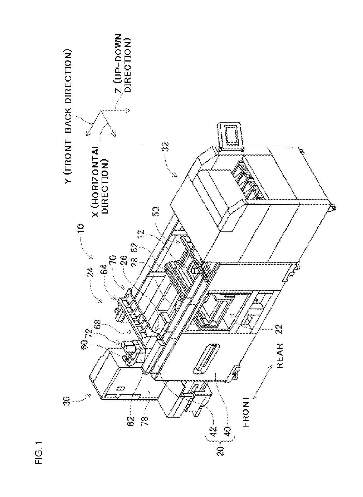
[0022]FIG. 1 illustrates a component mounting machine 10. The component mounting machine 10 is a device for executing mounting work of components onto a circuit substrate 12. The component mounting machine 10 is provided with a device main body 20, a substrate conveyance and holding device 22, a component mounting device 24, imaging devices 26 and 28, a component supply device 30, a bulk component supply device 32, and a control device 34 (refer to FIG. 8). Examples of the circuit substrate 12 include a circuit board, a three-dimensional structure substrate, and the like, and examples of the circuit board include a printed wiring board, a printed circuit board, and the like.

[0023]The device main body 20 is formed of a frame section 40, and a beam section 42 which bridges over the frame section 40. The substrat...


PUM


Abstract

A component supply device including a component storage device that stores a plurality of components, a component support member on which the components from the component storage device are dispersed, and a component return device that returns the components on the component support member to the component storage device, is provided. In a case where the necessary number of components exceeds the number of holdable components, return work of the components to the component container and dispersal work of the components to the component support section are carried out prior to holding the components from the component support section by the component holding tool.

Description

CROSS-REFERENCE TO RELATED APPLICATIONS[0001]This application is a continuation of U.S. application Ser. No. 15 / 554,386 filed Aug. 29, 2017, the entire contents of which is incorporated herein by reference. U.S. application Ser. No. 15 / 554,386 is a 371 of International Application No. PCT / JP2015 / 056161 filed Mar. 3, 2015.TECHNICAL FIELD[0002]The present disclosure relates to a mounting work machine that performs mounting work of components on a board.BACKGROUND ART[0003]In a component supply device that has a component support section that supports multiple components in a dispersed state, the components are dispersed from a component container in the component support section, and components with a holdable posture are held by a component holding tool out of the components that are supported in the component support section. Next, supply of the components is carried out by placing the components that are held in the component holding tool in an ordered state in a placement section....

Claims


Application Information

Patent Timeline
Patent Type & Authority Applications(United States)
IPC IPC(8): H05K13/02H05K13/08H05K13/04B65G47/14
CPCH05K13/022H05K13/086H05K13/081H05K13/043B65G47/14H05K13/0495H05K13/0452H05K13/028
Inventor MATSUMOTO, TORUIWAKI, NORIAKI
Owner FUJI CORP
Learn More