
Stator assembly

a stator and assembly technology, applied in the direction of dynamo-electric machines, electrical apparatus, magnetic circuit shapes/forms/construction, etc., can solve the problems of low productivity and large amount of coils, and achieve the effects of simplifying the manufacturing process, reducing the amount of coils, and increasing productivity

Inactive Publication Date: 2018-08-09
CHAN WING HANG
View PDF4 Cites 3 Cited by
  • Summary
  • Abstract
  • Description
  • Claims
  • Application Information

AI Technical Summary

Benefits of technology

The patent relates to a stator which has a simple structure and requires fewer coils. The coils are wound around two separate cores, which are then engaged with each other. This reduces the number of coils and simplifies the manufacturing process, increases productivity and lowers costs. The technical effects of this invention are a more efficient and cost-effective stator assembly.

Problems solved by technology

In this way, large amount of coils is required, and the productivity is low.

Method used


Image

  • Stator assembly
  • Stator assembly
  • Stator assembly

Examples


Embodiment Construction

[0034]The present invention is further described in detail with the following embodiment and the accompanying drawings.

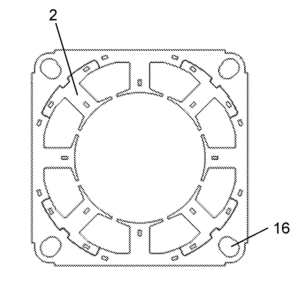
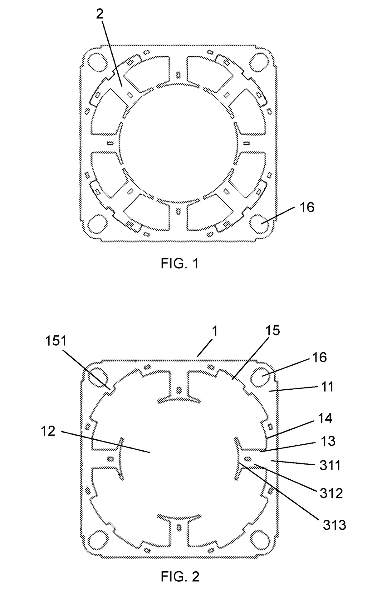
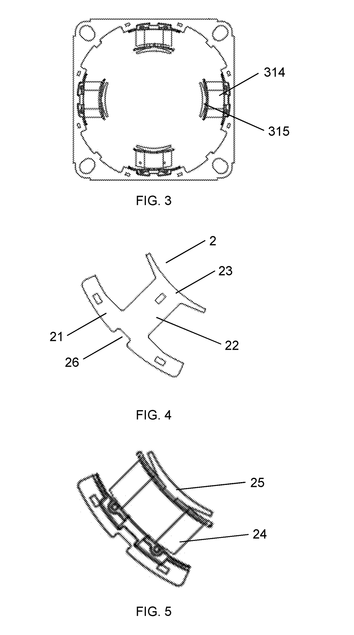
[0035]As illustrated in FIGS. 1-9, the stator assembly of the first embodiment comprises a first core member 1 and four second core members 2. The first core member 1 comprises a first core member body 11 having a substantially circular center through hole 12, four cores 13 integrally extended from an inner circumferential surface 14 of the center through hole 12 in an evenly spaced manner, and four arc-shaped receiving recesses 15 provided along the inner circumferential surface 14 of the center through hole 12, with each of the receiving recesses 15 arranged between each adjacent pair of cores 13; each of the cores 13 comprises a first yoke portion 311, a first tooth portion 312 extending from the first yoke portion 311 and having an arc-shaped end 313 opposite the first yoke portion 311, and a first coil 314 wound around a first insulating bobbin 315 provided bet...


PUM


Abstract

A stator assembly comprises a first core member and a plurality of second core members. The first core member comprises a first core member body, a plurality of cores and a plurality of receiving recesses. Each of the cores comprises a first yoke portion, a first tooth portion, a first coil and a first insulating bobbin. The second core member comprises a second yoke portion, a second tooth portion, a second coil and a second insulating bobbin. The first core member is engageable with the plurality of second core members in a manner such that the second yoke portions are fixedly received in the receiving recesses respectively with each of the second core members arranged interposed between each adjacent pair of cores so that the arc-shaped ends of the first tooth portions and the second tooth portions form an annular shape.

Description

BACKGROUND OF THE INVENTION[0001]The present invention relates to electric motors and more particularly pertains to a structure of a stator for use in electric motors.[0002]Currently, during stator manufacturing process, stator windings are molded and thereafter inserted into stator groove manually. In this way, large amount of coils is required, and the productivity is low.BRIEF SUMMARY OF THE INVENTION[0003]In view of the aforesaid disadvantages now present in the prior art, the object of the present invention is to provide a stator which is simple in structure, requires less coils and easier to manufacture.[0004]To attain this, the present invention comprises[0005]a first core member comprising a first core member body having a substantially circular center through hole, a plurality of cores integrally extended from an inner circumferential surface of the center through hole in an evenly spaced manner, and a plurality of arc-shaped receiving recesses provided along the inner circ...

Claims


Application Information

Patent Timeline
Patent Type & Authority Applications(United States)
IPC IPC(8): H02K1/14H02K1/18H02K3/18
CPCH02K1/146H02K3/18H02K1/182H02K1/148H02K3/522
Inventor CHAN, WING HANG
Owner CHAN WING HANG
Learn More