
Rotation control systems for surgical instruments

a technology of rotation control system and surgical instrument, which is applied in the field of surgical instruments, can solve problems such as fatigue or stress in the fingers of surgeons

Active Publication Date: 2018-05-17
TYCO HEALTHCARE GRP LP
View PDF4 Cites 209 Cited by
  • Summary
  • Abstract
  • Description
  • Claims
  • Application Information

AI Technical Summary

Benefits of technology

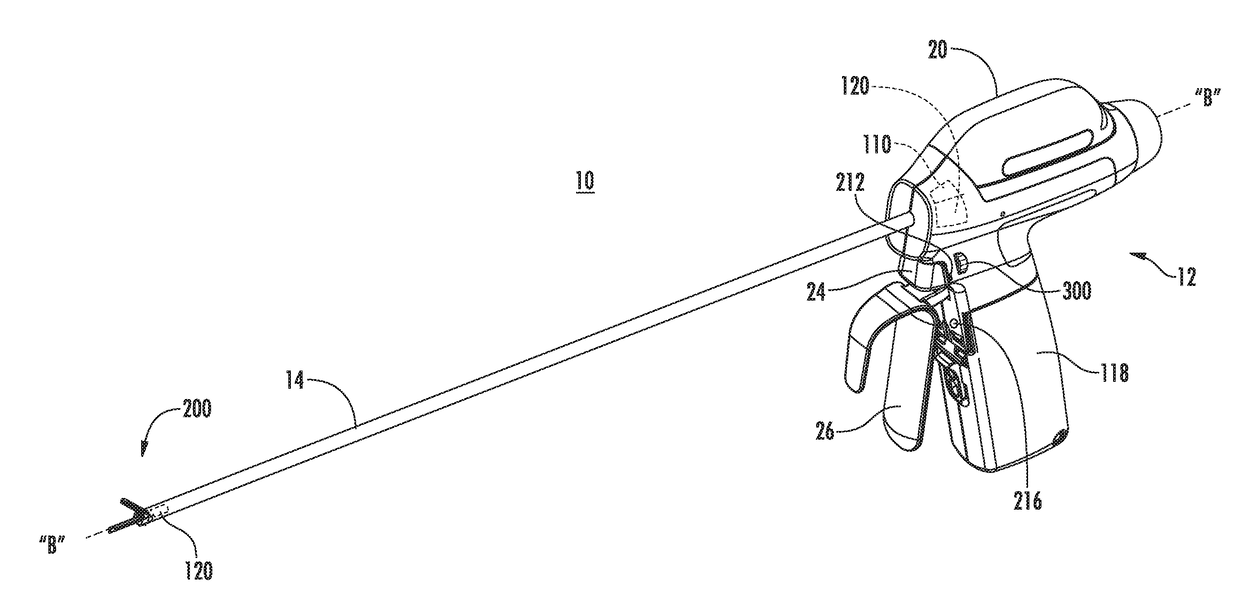
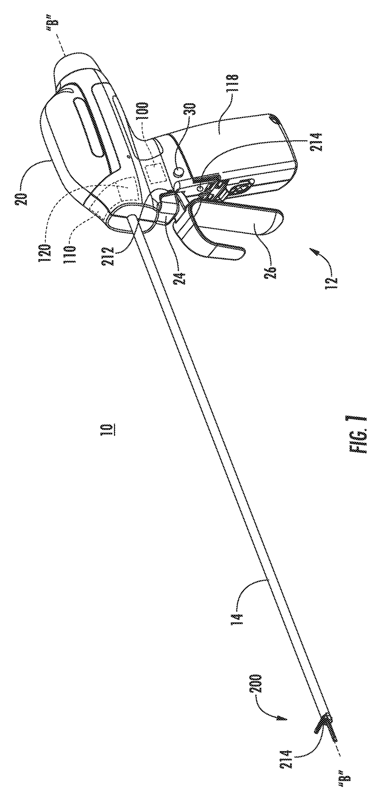
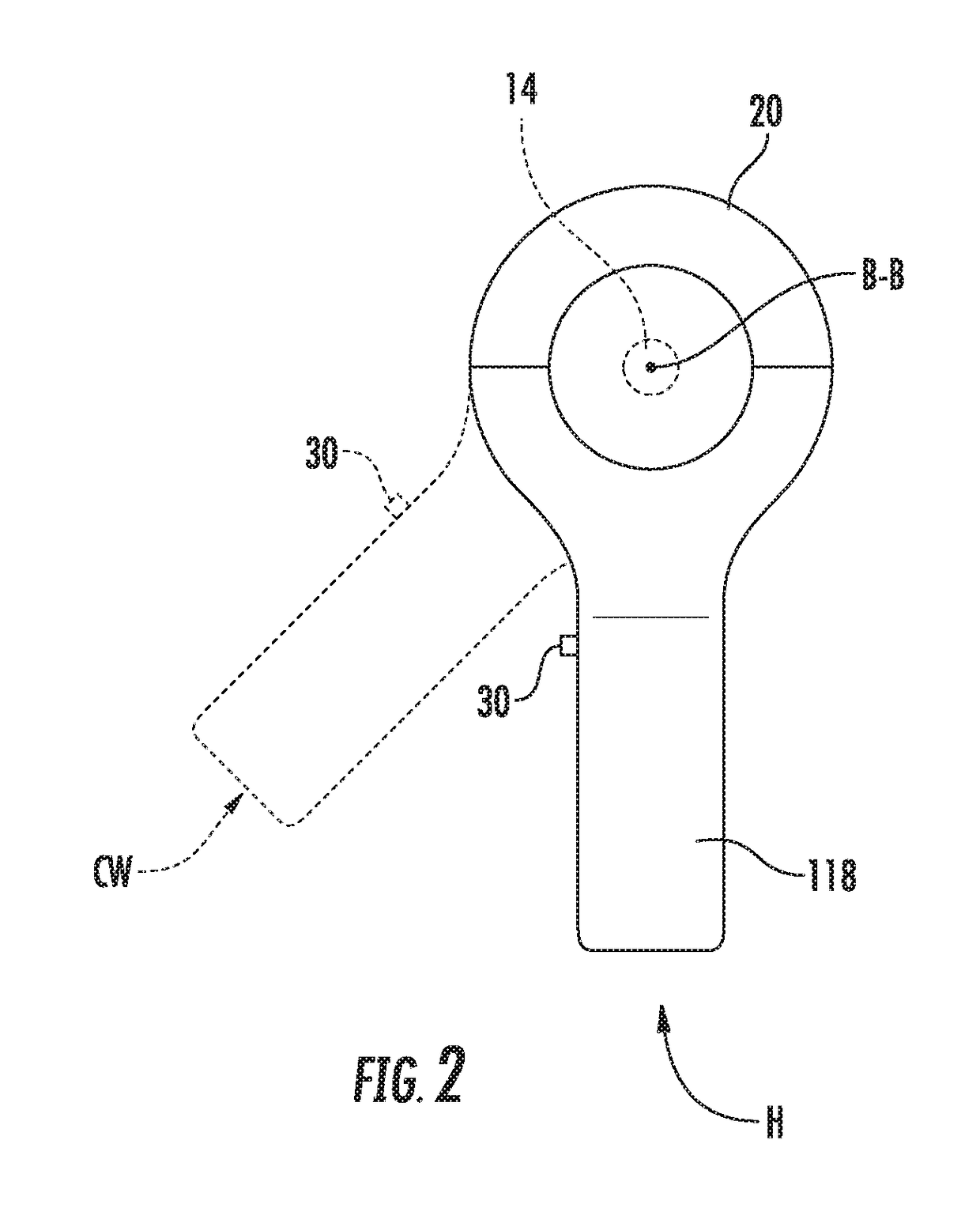
The surgical instrument described in this patent has a motion activation control that can be used to define a home position for the instrument. It also includes a rotation lockout that prevents the instrument from rotating when the jaw is in a clamping position. The instrument can be activated by a clamp trigger or an activation button to deliver energy to the end effector. The rotation lockout prevents the instrument from rotating when the clamp trigger or activation button is engaged. Overall, this design allows for precise and safe use of the surgical instrument.

Problems solved by technology

The technical problem addressed in this patent text is the need to reduce fatigue or stress in the fingers of surgeons who use endoscopic instruments with rotation features.

Method used


Image

  • Rotation control systems for surgical instruments
  • Rotation control systems for surgical instruments
  • Rotation control systems for surgical instruments

Examples


Embodiment Construction

[0017]Embodiments of the present disclosure are now described in detail with reference to the drawings in which like reference numerals designate identical or corresponding elements in each of the several views. As used herein, the term “clinician” refers to a doctor, a nurse, or any other care provider and may include support personnel. Throughout this description, the term “proximal” refers to the portion of the device or component thereof that is closest to the clinician and the term “distal” refers to the portion of the device or component thereof that is farthest from the clinician.

[0018]This disclosure relates generally to an endoscopic surgical instrument including a motor assembly that rotates an end effector of the surgical instrument in response to inputs of a clinician. The surgical instrument can include a motion sensing assembly that senses movement of a handle assembly of the surgical instrument from a home position and rotates the end effector in response to the sense...


PUM


Abstract

A surgical instrument includes a handle assembly, an elongate member, and a motor assembly. The elongate member extends from the handle assembly and defines a longitudinal axis of the surgical instrument. The motor assembly is disposed within the handle assembly and is configured to rotate the elongate member about the longitudinal axis relative to that handle assembly in response to sensed movement of the handle assembly about the longitudinal axis.

Description


Claims


Application Information

Patent Timeline
Owner TYCO HEALTHCARE GRP LP
Learn More