Automated work piece moment of inertia (MOI) identification system and method for same

a technology of inertia and identification system, which is applied in the direction of instruments, apparatus for force/torque/work measurement, and structures/machines measurement, etc., can solve the problems of difficult assembly model, complex determination of moi and poi,

Active Publication Date: 2018-04-19
RAYTHEON CO
View PDF2 Cites 17 Cited by
  • Summary
  • Abstract
  • Description
  • Claims
  • Application Information

AI Technical Summary

Benefits of technology

The patent text describes a system and method for accurately identifying the moment of inertia (MOI) and products of inertia (POI) of a work piece, which is important for controlling the assembly of the work piece. The system uses load tables to measure the MOI and POI of the work piece when it is assembled. The assembly is then fixed to a table and rotated to preload a calibrated torsion bar. The frequency of the UUT oscillation is used to determine the MOI of the UUT. The technical effect of this patent is to provide a reliable and automated way to identify the MOI and POI of work pieces, which is critical for precise control during assembly, launch, and operation.

Problems solved by technology

Determination of the MOI and POI is much more complex when parts are incorporated as a whole into an overall assembly.
The assembly is difficult to model because of the various orientations of the parts and the varying materials.

Method used


Image

  • Automated work piece moment of inertia (MOI) identification system and method for same
  • Automated work piece moment of inertia (MOI) identification system and method for same
  • Automated work piece moment of inertia (MOI) identification system and method for same

Examples


Embodiment Construction

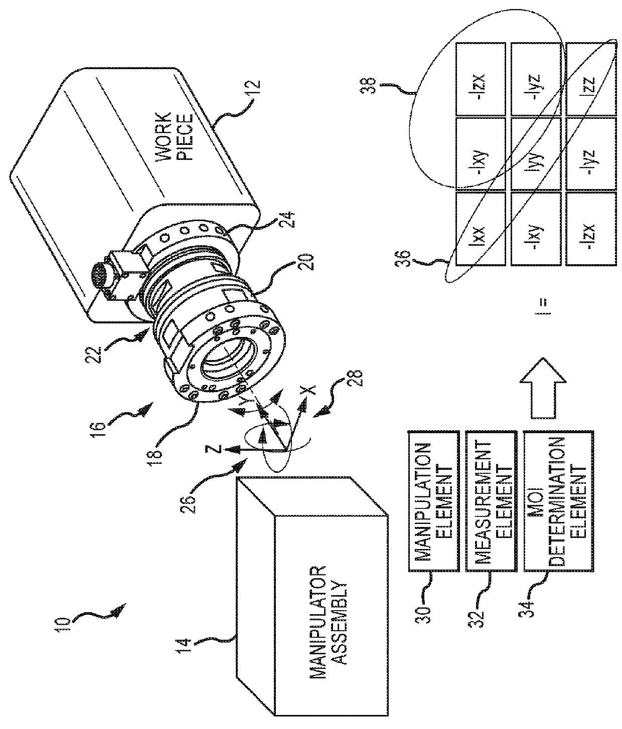
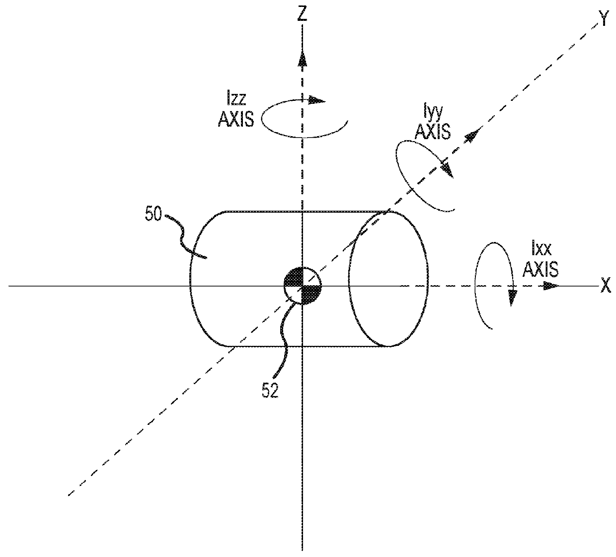
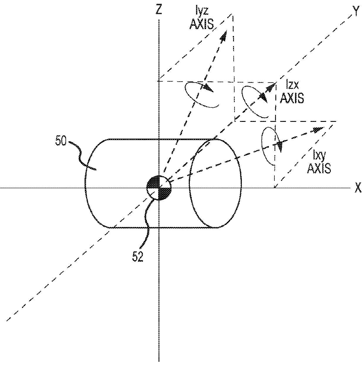
[0018]Load tables are used to measure moment of inertia (MOI) and products of inertia (POI) with assemblies or “work pieces” having one or more component parts assembled together. The assembly is brought to a facility having a load table of sufficient size and capacity to carry the assembly (e.g., in some example configured to weigh thousands of pounds). The assembly is fixed to the table (e.g., bolted) to ensure the assembly remains in a particular orientation. The unit is rotated on a rotational air bearing to preload a calibrated torsion bar. The unit is released and begins to pendulum as torsional energy is released and stored in the torsion bar. The frequency of this UUT oscillation is used to determine the MOI of the UUT. The unit is then removed and reinstalled to a different orientation. The process is repeated to measure the MOI around the second axis. The reorientation is done a third time to measure MOI for the last axis. The entire process may be repeated at 45-degree ro...


PUM


Abstract

A method and system for identifying a moment of inertia (MOI) of a work piece includes coupling the work piece to a manipulator assembly such as a 6-axis robotic arm or 3-axis gimbal. The manipulator assembly includes a force / torque sensor and a motion feedback sensor. The manipulator assembly moves the work piece with three-dimensional motion. Force, torque and movement measurements are made as the work piece moves. The MOI is identified according to the force and torque measurements and rotational accelerations derived from the measured movement. The measurements may be used to identify the products of inertia (POI) and center of mass of the work piece.

Description

RELATED APPLICATIONS[0001]This application claims benefit of priority under 35 U.S.C. 119(e) to U.S. Provisional Application No. 62 / 409,317 entitled “AUTOMATED WORK PIECE MOMENT OF INERTIA (MOI) IDENTIFICATION SYSTEM AND METHOD FOR SAME” and filed on Oct. 17, 2016, the entire contents of which are incorporated by reference.[0002]This application is related to U.S. application Ser. No. 14 / 689,125 entitled “AUTOMATED WORK PIECE CENTER OF MASS IDENTIFICATION SYSTEM AND METHOD FOR SAME” and filed on Apr. 17, 2015, the entire contents of which are incorporated by reference.BACKGROUND OF THE INVENTIONField of the Invention[0003]This document pertains generally, but not by way of limitation, to the determination of the moment of inertia (MOI) for a work piece and in some instances to the determination of the center of mass / center of gravity (CG) or products of inertia (POI) for the work piece.Description of the Related Art[0004]Determining the moment of inertia (MOI) and products of inerti...

Claims


Application Information

Patent Timeline
IPC IPC(8): B25J13/08G01L5/22B25J11/00G01M1/12
CPCB25J13/085G01M1/122B25J11/00G01L5/226G01M1/10
Inventor VULCANO, ANTHONY R.HOLYOAK, VONN L.MOOSMAN, BRYAN R.
Owner RAYTHEON CO
Why Eureka
Try Eureka