
Intermediate casing for a turbomachine turbine

Active Publication Date: 2018-03-08
SN DETUDE & DE CONSTR DE MOTEURS DAVIATION S N E C M A
View PDF0 Cites 1 Cited by
  • Summary
  • Abstract
  • Description
  • Claims
  • Application Information

AI Technical Summary

Benefits of technology

The invention aims to provide a simple, efficient and economical solution to a problem that needs to be solved.

Problems solved by technology

Such attachment however has a major drawback.
An axial misalignment of the casings can then create disturbances in the circulation of the air flow, impacting the efficiency of the turbine, and thus, that of the turbomachine.
Besides, such misalignment can be increased by the deformation, caused by heat, of the casings when the turbine is operating.

Method used


Image

  • Intermediate casing for a turbomachine turbine
  • Intermediate casing for a turbomachine turbine
  • Intermediate casing for a turbomachine turbine

Examples


Embodiment Construction

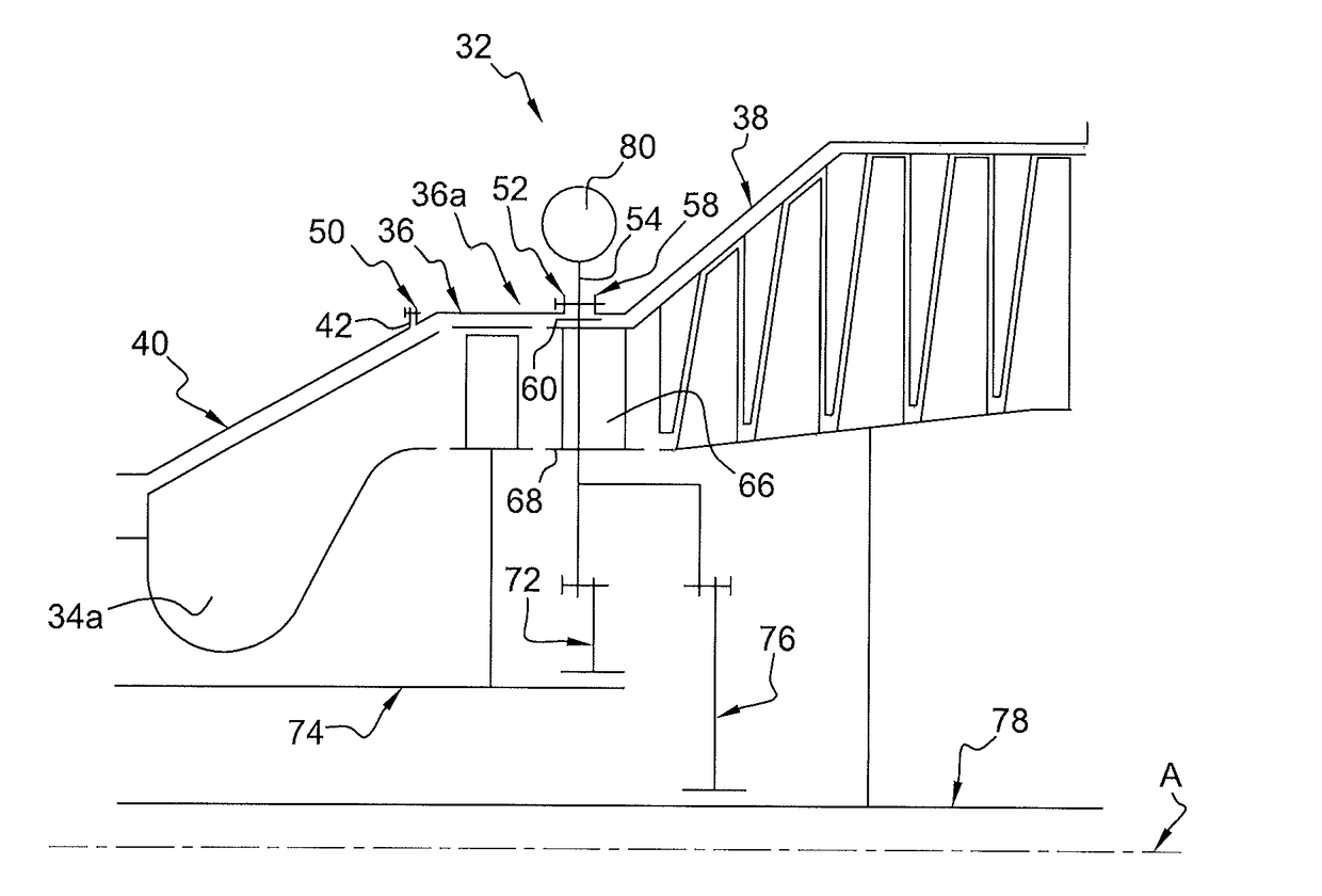
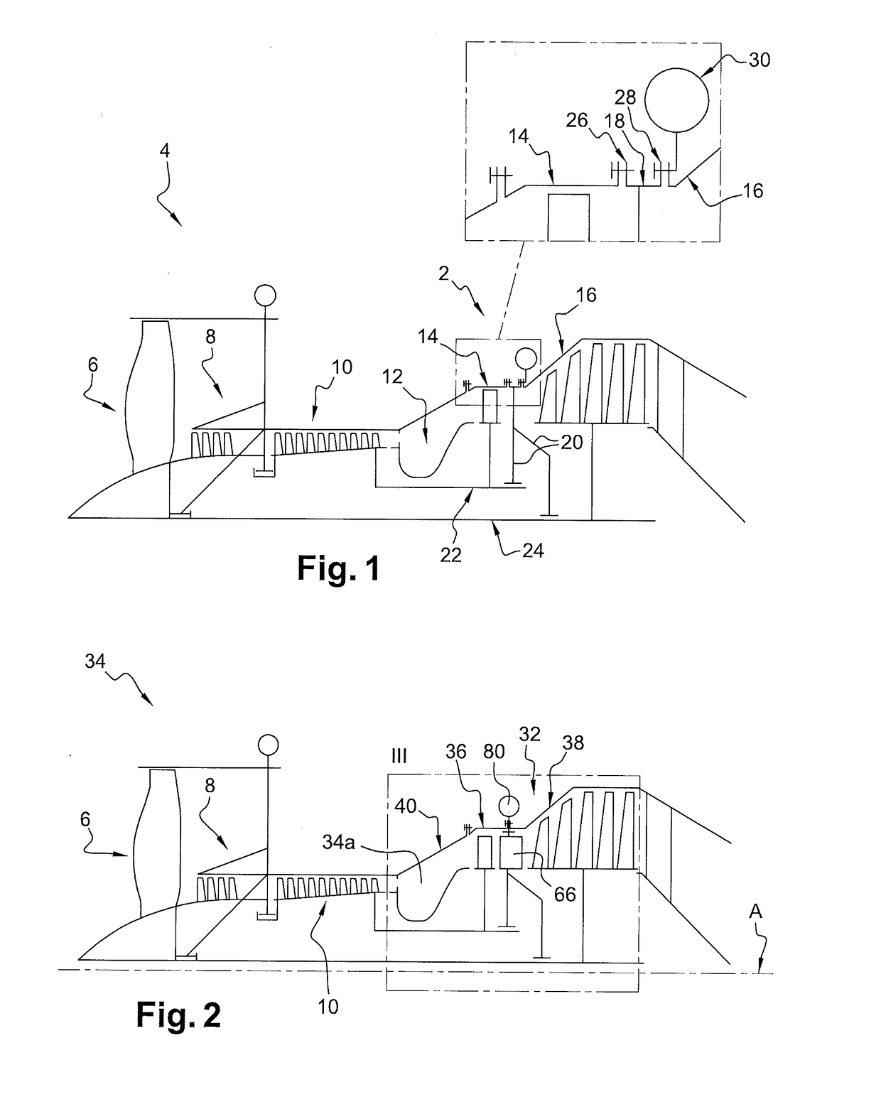
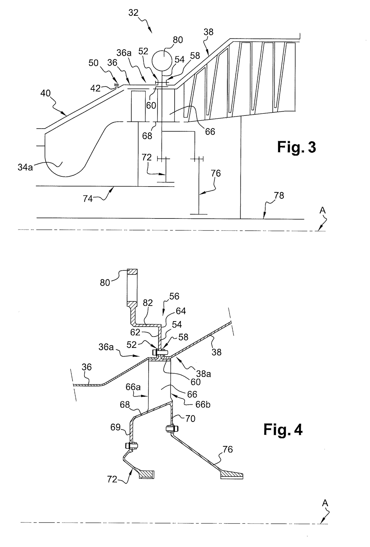
[0038]FIGS. 2 and 3 show a turbine 32 of a turbomachine 34. The turbomachine 34 comprises a combustion chamber 34a opening downstream into a high pressure turbine externally delimited by a high pressure turbine casing 36, here casing 36 HP, then into a low pressure turbine externally delimited by a low pressure turbine casing 38, here casing 38 BP. As illustrated, the downstream end of the combustion chamber casing 40 is attached by an annular flange 42 bolted on an annular flange 50 of the upstream end of the casing 36 HP. The downstream end 36a of the casing 36 HP comprises a radial annular flange 52 attached on a radial annular flange 54 of a structural intermediate casing 56, here intermediate casing 56, inserted between the casing 36 HP and the casing 38 BP (FIG. 4).

[0039]The turbine 32 here combines the high pressure turbine and the low pressure turbine.

[0040]Like that of the prior art, the turbomachine 34 comprises a fan disc 6 sucking air towards a downstream low pressure co...


PUM


Abstract

A turbine comprising an intermediate casing axially inserted between an upstream high pressure turbine casing and a downstream low pressure turbine casing and comprising an outer annular shroud from which an annular flange radially extends, characterized in that the downstream end of the high pressure turbine casing and the upstream end of the low pressure turbine casing are attached on the radial annular flange of the intermediate casing.

Description

FIELD OF THE INVENTION[0001]The present invention relates to a turbomachine turbine, and specifically to attaching various casings of such turbine together.BACKGROUND OF THE INVENTION[0002]A turbine generally comprises several successive casings along the longitudinal axis of the turbine, such casings provide protection to the turbine elements or form flow paths or veins wherein air flows through the turbine.[0003]Such casings are generally annular, extend along the longitudinal axis of the turbine, and have to be perfectly aligned so as to limit disturbances in the air flow, more particularly when the casings form flow paths or veins.[0004]The casings each comprise an annular flange through which they are assembled together by bolting.[0005]In a junction area of the downstream end of the combustion chamber casing with a turbine casing, as schematically illustrated in FIG. 1 which shows a turbomachine 4 turbine 2 of the prior art, the turbomachine comprises a fan disc 6 sucking air ...

Claims


Application Information

Patent Timeline
IPC IPC(8): F01D25/24F01D25/28F01D25/16
CPCF01D25/243F01D25/28F01D25/16F05D2220/323F05D2240/14F05D2240/90F05D2230/53F01D25/24F01D25/162Y02T50/60
Inventor BLANCHARD, STEPHANE PIERRE GUILLAUMECONDAT, HELENE MYRIAM
Owner SN DETUDE & DE CONSTR DE MOTEURS DAVIATION S N E C M A
Learn More