Lane Departure Warning System And Associated Methods
- Summary
- Abstract
- Description
- Claims
- Application Information
AI Technical Summary
Benefits of technology
Problems solved by technology
Method used
Image
Examples
Embodiment Construction
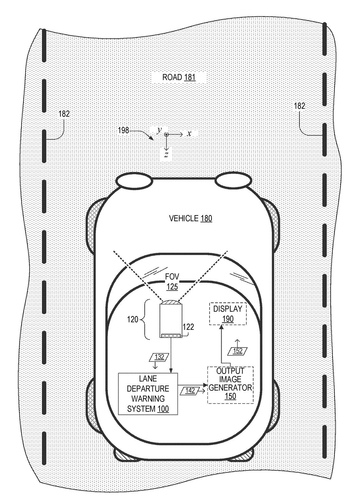
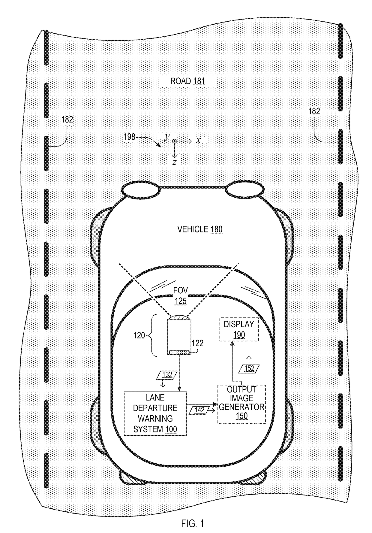
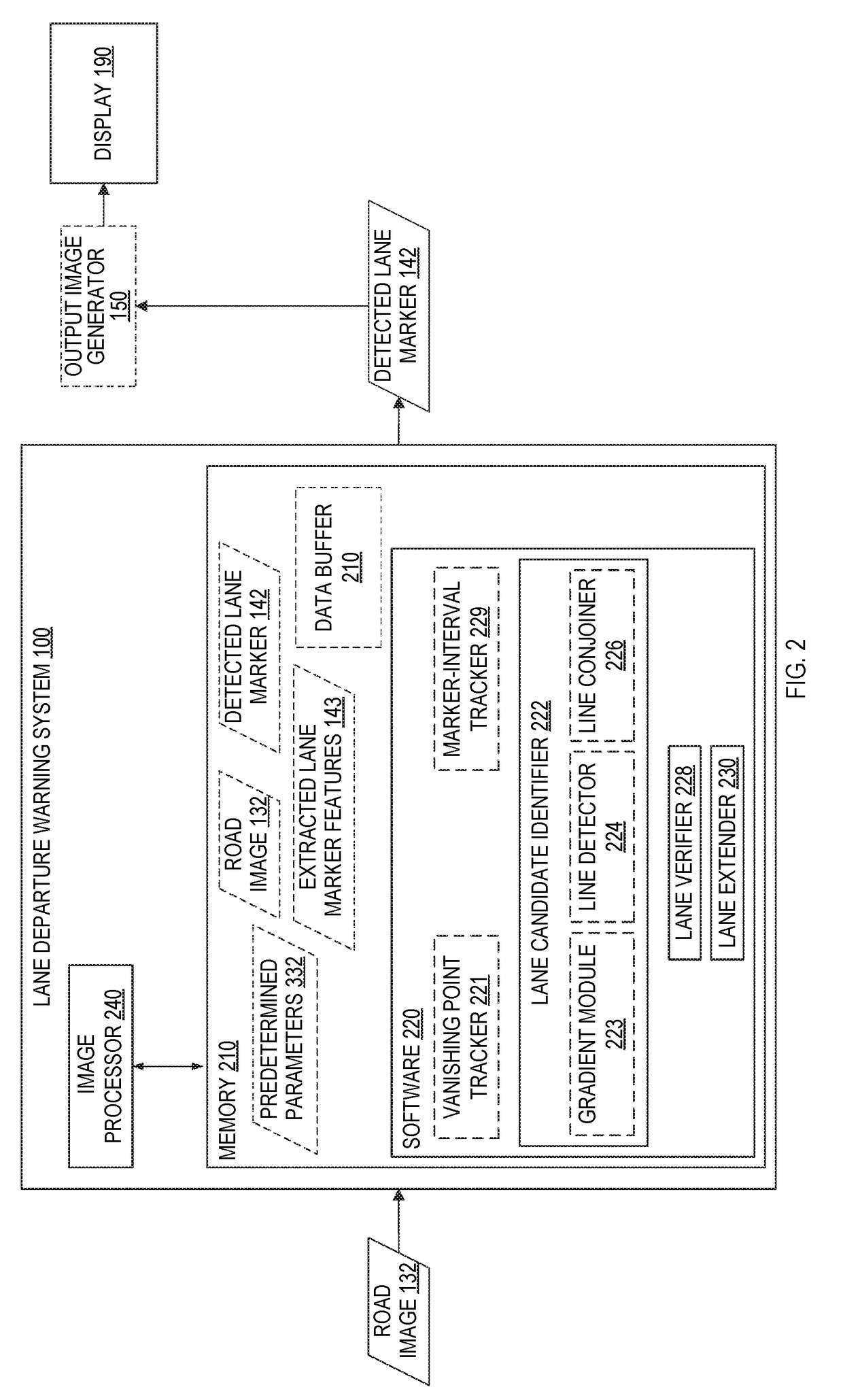
[0026]FIG. 1 is a plan view showing one exemplary lane departure warning system 100 used within a vehicle 180. Vehicle 180 is on a road 181 that has lane markers 182, which are in a plane parallel to the x-z plane of a coordinate system 198. Herein, references to x, y, and z refer to coordinate system 198 unless otherwise specified. Lane departure warning system 100 includes an image processor 240. Vehicle180 includes a camera 120 and optionally a display 190 communicatively coupled to lane departure warning system 100. Camera 120 includes an image sensor having a pixel array 122. In an embodiment, lane departure warning system 100 includes at least one of camera 120 and display 190. Herein, a lane marker is also referred to as a marker for sake of brevity.
[0027]Lane departure warning system 100 receives a road image 132 of a portion of road 181 within a field of view 125 of camera 120. Lane departure warning system 100 processes at least part of road image 132 to detect one or more...
PUM
 Abstract
Description
Claims
Application Information
 - R&D
- Intellectual Property
- Life Sciences
- Materials
- Tech Scout
- Unparalleled Data Quality
- Higher Quality Content
- 60% Fewer Hallucinations
Browse by: Latest US Patents, China's latest patents, Technical Efficacy Thesaurus, Application Domain, Technology Topic, Popular Technical Reports.
© 2025 PatSnap. All rights reserved.Legal|Privacy policy|Modern Slavery Act Transparency Statement|Sitemap|About US| Contact US: help@patsnap.com


